
System for navigation of an autonomously navigating submersible body during entry into a docking station, method

a technology for autonomous navigation and submersibles, applied in special purpose vessels, instruments, image enhancement, etc., can solve problems such as damage to underwater equipment or mothers, underwater equipment swinging during hauling up, and hitting the ship's side, so as to improve control, reduce the effect of battery capacity and simplify the determination of the actual motion vector

Active Publication Date: 2021-03-09
FRAUNHOFER GESELLSCHAFT ZUR FOERDERUNG DER ANGEWANDTEN FORSCHUNG EV
View PDF68 Cites 0 Cited by
  • Summary
  • Abstract
  • Description
  • Claims
  • Application Information

AI Technical Summary

Benefits of technology

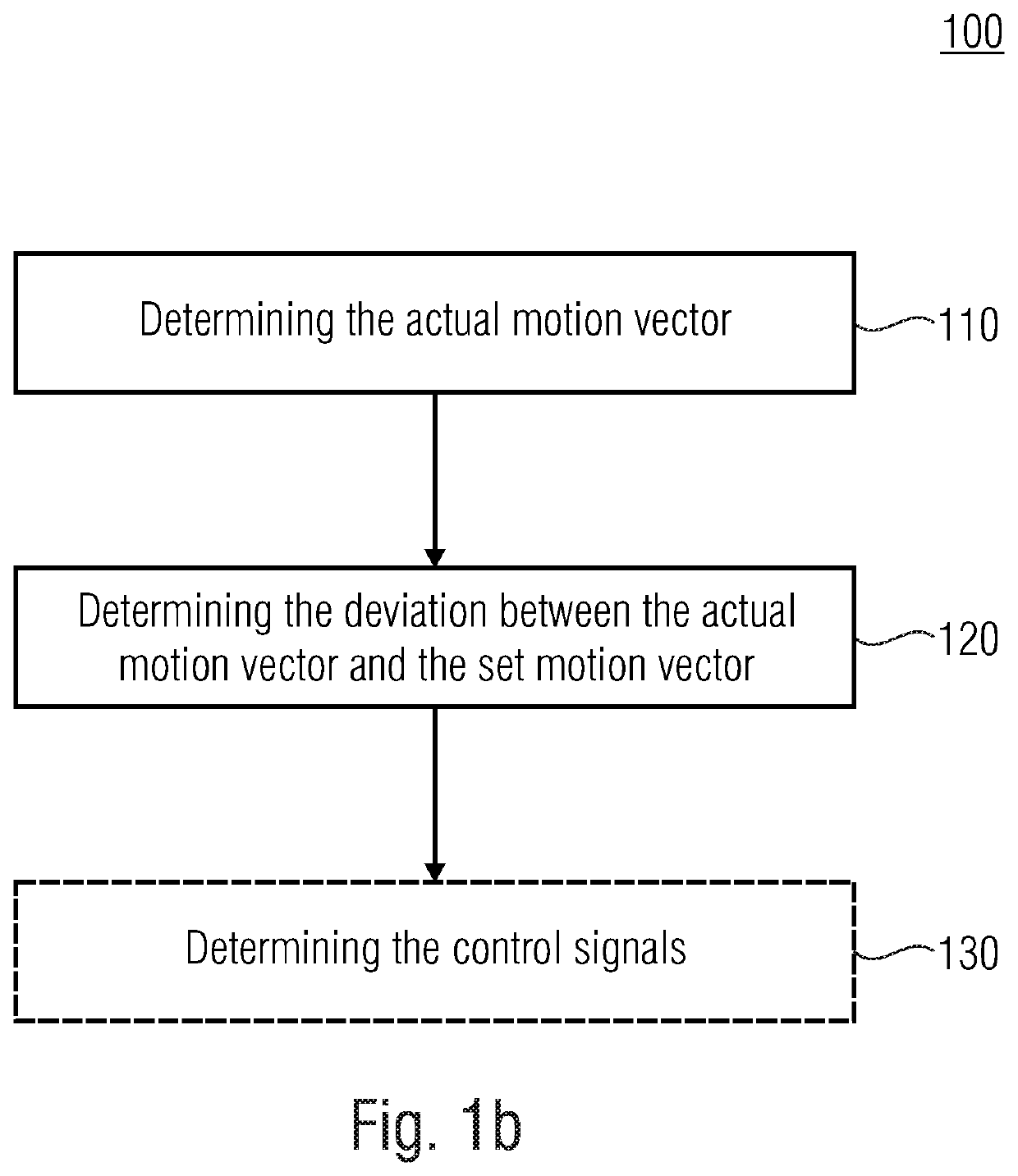
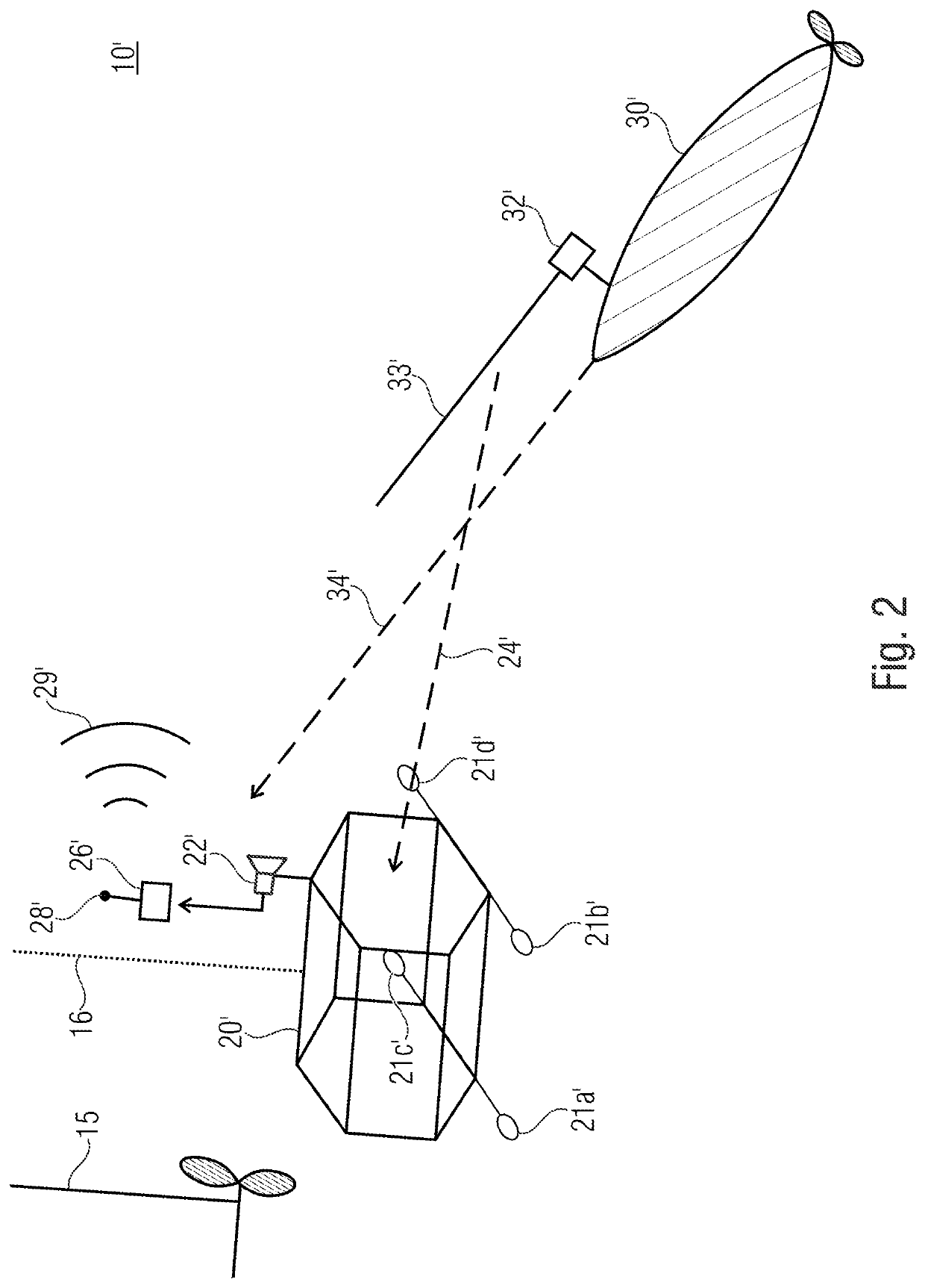
[0014]Embodiments of the present invention are based on the knowledge that it has been found out that retrieving autonomously navigating submersible bodies, AUVs, below the water surface can be performed significantly easier when the problem of exact determination of the motion direction of the autonomously navigating submersible body in relation to the catching station and thus improved control of the same is solved. Monitoring and localizing the autonomously navigating submersible body is performed with the help of sensors, such as one or several cameras or a sonar device attached to the docking station. Since the camera is mounted to the docking station, the relation between the perspective of the same and a so-called set motion vector describing the optimum entry direction for an autonomously navigating submersible body into the docking station is known. When monitoring the autonomously navigating submersible body, the actual motion direction and the actual motion vector of autonomously navigating submersible body can be determined, such that by the relation between the actual motion vector and the set motion vector, a deviation between the same can be determined in order to control the AUV based on this determined deviation. Here, in the near range of the docking station, the autonomous operation of the AUV is switched to the remote control mode, i.e., the AUV is controlled from the docking station, for example per (acoustic) modem. This approach enables secure and reliable retrieval of the AUV below the water. Retrieval below the water is advantageous since the drives of the AUV are frequently too weak to fight against the forces at the water surface, for example in rough weather. Providing the sensor technology, such as the camera, at the docking station is advantageous since the AUV has only very limited options for mounting the sensor technology, for space reasons or due to the low battery capacity.
[0016]According to further embodiments, the docking station can also include an interface to the autonomously navigating submersible body via which the autonomously navigating submersible body can be charged or data exchanges performed. This is possible since the docking station, e.g., in the form of a cage, can be simply hauled along the boat together with the autonomously navigating submersible body without any damages of mother ship, docking station or autonomously navigating submersible body since both the docking station and the autonomously navigating submersible body are hauled along safely under the water surface.
[0019]According to further embodiments, the system can be configured to very effectively slow down the autonomously navigating submersible body when entering the docking station. Here, it has been found to be advantageous to span an arresting rope that is mounted, for example with shock absorbers on the cage, within the cage, such that the autonomously navigating submersible body can be slowed down by this arresting rope. For this, the autonomously navigating submersible body can comprise, for example, a hook or can fold out a hook, such that good engagement results between the arresting rope and the autonomously navigating submersible body. Therefore, the control is configured to fold out the hook as soon as the autonomously navigating submersible body enters the cage in order to perform the braking action. Slowing down is needed because the autonomously navigating submersible body can only be controlled when a certain incident flow at the fins exists. For this, the autonomously navigating submersible body needs a minimum velocity of, for example 1 kn, even when entering the docking station.

Problems solved by technology

This process does not work satisfactorily when dealing with heavy and sensitive underwater equipment in rough water.
Firstly, it is very likely that the underwater equipment swings during the lifting or lowering process, comes into contact with the ship and damages at the underwater equipment or mother ship result, also due to the different amplitudes and frequency responses of the two objects.
There is a risk that the underwater equipment swings during hauling up and hits against the ship's side.
This can also cause significant damages at the heavy but sensitive structure of both the underwater vehicle and the mother ship.
The costs for the ship are approximately 50 k € a day such that the need to wait has great economic disadvantages.
As soon as the crane rope is retrieved, a stopper attached to the rope gets caught in the eye.

Method used


Image

  • System for navigation of an autonomously navigating submersible body during entry into a docking station, method
  • System for navigation of an autonomously navigating submersible body during entry into a docking station, method
  • System for navigation of an autonomously navigating submersible body during entry into a docking station, method

Examples


Embodiment Construction

[0028]Before embodiments of the present invention will be discussed below based on the figures, it should be noted that equal elements and structures are provided with the same reference numbers such that the description of the same is interapplicable or exchangeable.

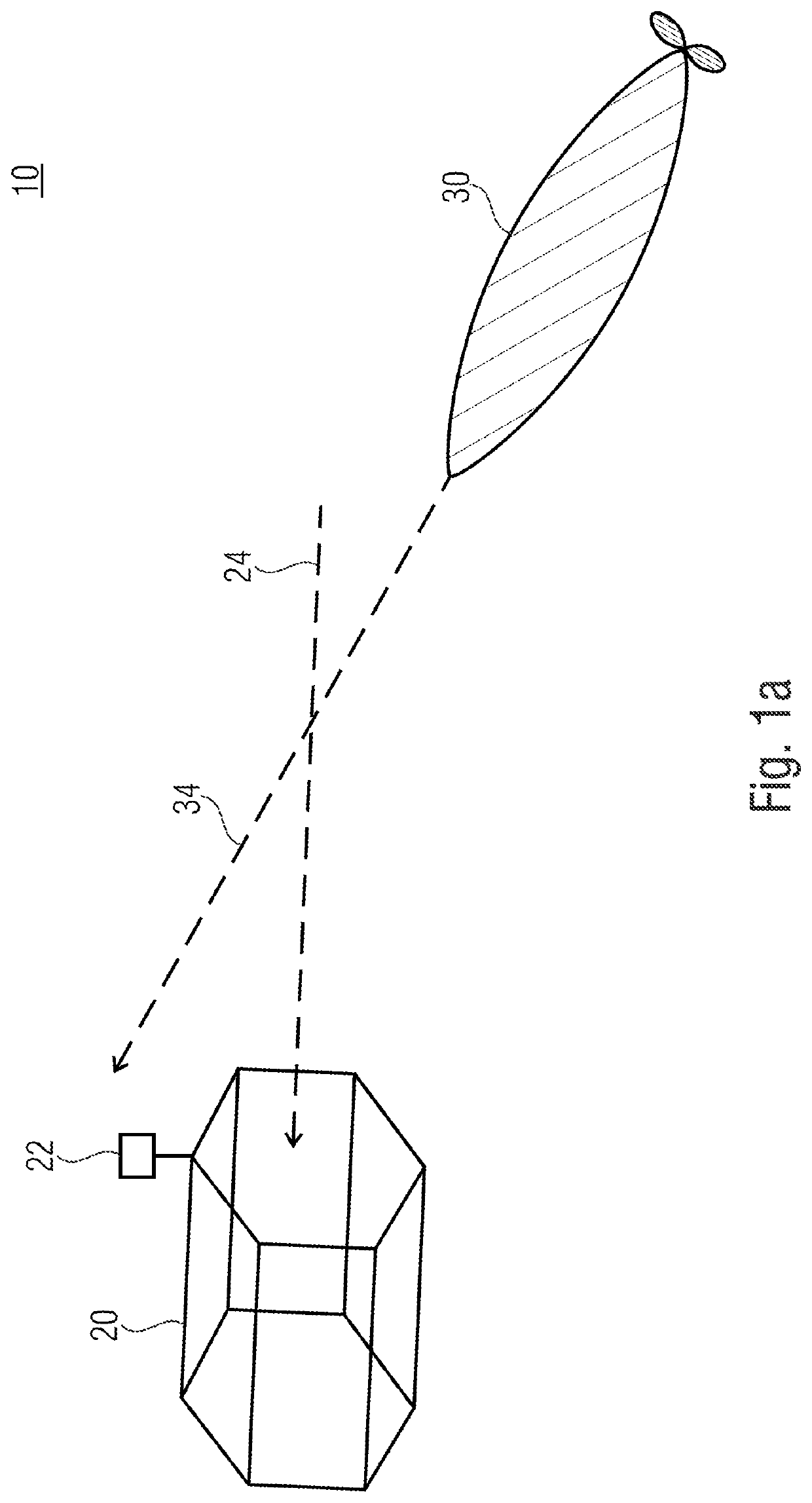
[0029]FIG. 1a shows a system 10 with a docking station 20 and an autonomously navigating submersible body 30.

[0030]In this embodiment, the docking station 20 is configured, for example as tube-shaped or honeycomb-shaped structure and serves to capture and retrieve the autonomously navigating submersible body 30 as well as to protect the same from waves and flotsam and also the collision of the autonomously navigating submersible body 30 with the ship's side of the mother ship (not shown). Typically, the catching station 20 is at least as long as the autonomously navigating submersible body 30. At the beginning of the retrieving action, the autonomously navigating submersible body 30 is below the spume and wave zone in a...


PUM


Abstract

A system for navigation of an autonomously navigating submersible body during entry into a docking station below the water surface includes a determiner for determining an actual motion vector of the autonomously navigation submersible body in relation to the set motion vector describing the optimum entry direction into the docking station and a calculating unit. The calculating unit serves to determine the deviation between the actual motion vector and the set motion vector to determine control vectors based on the deviation and to thereby control the autonomously navigating submersible body during entry.

Description

CROSS-REFERENCE TO RELATED APPLICATIONS[0001]This application is a continuation of copending International Application No. PCT / EP2017 / 057599, filed Mar. 30, 2017, which is incorporated herein by reference in its entirety, and additionally claims priority from European Application No. 16163313.6, filed Mar. 31, 2016, which is also incorporated herein by reference in its entirety.[0002]Embodiments of the present invention relate to a system for navigation of an autonomously navigating submersible body when entering a docking station below the water surface as well as an associated method. Further embodiments relate to an apparatus for retrieving a driving autonomously navigating submersible body below the water surface.BACKGROUND OF THE INVENTION[0003]Many lowering and retrieving apparatuses for manned and unmanned submersible or diving vehicles use deck cranes operating via the lateral ship's side or tail of the mother ship. This process does not work satisfactorily when dealing with...

Claims


Application Information

Patent Timeline
Patent Type & Authority Patents(United States)
IPC IPC(8): G05D1/06B63G8/00B63G8/14G06T7/246B63C1/12G01S15/58B63B27/16H04N5/225
CPCG05D1/0692B63C1/12B63G8/001B63G8/14G01S15/58G06T7/246B63B2027/165B63G2008/002B63G2008/004B63G2008/005B63G2008/008G06T2207/30232G06T2207/30252H04N5/225H04N23/00
Inventor BEYERER, JUERGENBRINK, GUNNAR
Owner FRAUNHOFER GESELLSCHAFT ZUR FOERDERUNG DER ANGEWANDTEN FORSCHUNG EV
Learn More