Scanning X-ray apparatus with full-field detector

a detector and scanning x-ray technology, applied in the field of scanning x-ray equipment, can solve the problems of high cost, difficult alignment procedures, and relatively limited system size, and achieve the effect of softening the accuracy requirements for movemen

Active Publication Date: 2021-03-16
KONINKLJIJKE PHILIPS NV
View PDF17 Cites 0 Cited by
  • Summary
  • Abstract
  • Description
  • Claims
  • Application Information

AI Technical Summary

Benefits of technology

[0009]In other words, it is proposed herein to use a relatively large X-ray detector (possibly a full field X-ray detector) in combination with a relatively small (that is, compared to the field of view of the X-ray detector) interferometer, which interferometer during an imaging operation is being moved by the apparatus across the field of view for scanning purposes. Since the detector pixels are not moving during said imaging operation, the X-ray imaging apparatus advantageously prevents from motion blur in full. Accordingly, an expensive X-ray detector providing for a high detector read-out, which would ordinarily be required in prior art scanning systems for suppressing motion blur, is effectively circumvented by the X-ray imaging apparatus according to the present invention. Consequently, contrary to prior art scanning systems in which scanning time is inversely proportionally related to the detector read-out, in the X-ray imaging apparatus according to the present invention scanning time is related to the speed at which fringes, as generated by the interferometer during operation, move across the X-ray detector. This enables a shorter scan time which is notably beneficial for mammography during which the breast is held in painful compression hence in view of which scan time should be kept at a minimum. For instance, given a reasonable dimension (in the scanning direction) of the interferometer of about 40 mm, it is then reasonable for a scanning system that two fringe periods are generated across these 40 mm. With a modest readout in the order of eight readouts per fringe period, one can achieve a readout for every 2.5 mm of scan motion, which is more than an order of magnitude less demanding than in prior art scanning systems. This is because in an prior art scanning system, the detector moves as well and a readout is required at the rate at which the X-ray detector moves over a distance equal to the pixel size, which is typically in the order of 50 μm (in case of mammography) to 200 μm (in case of radiography).
[0026]According to another embodiment of the X-ray imaging apparatus, the X-ray imaging apparatus is further configured to effect, during an imaging operation, the at least one grating to move in the scanning motion relative to the X-ray detector to such extent that said at least one grating is not impacted by the beam of X-ray radiation during operation. This example has the effect of enabling switching from differential phase contrast imaging and / or dark field imaging to conventional radiology i.e. projection imaging, and vice versa.

Problems solved by technology

However some of these systems are still relatively expansive due to the required component performance.
For instance, full field systems (see for instance Ewald Roessl, “Clinical boundary conditions for grating-based differential phase-contrast mammography” in Philosophical Transactions A, 6 Mar. 2014, volume 372, issue 2010) have good flux properties and afford relatively quick data acquisition but require large grating structures, which imply high cost and difficult alignment procedures.

Method used


Image

  • Scanning X-ray apparatus with full-field detector
  • Scanning X-ray apparatus with full-field detector
  • Scanning X-ray apparatus with full-field detector

Examples


Embodiment Construction

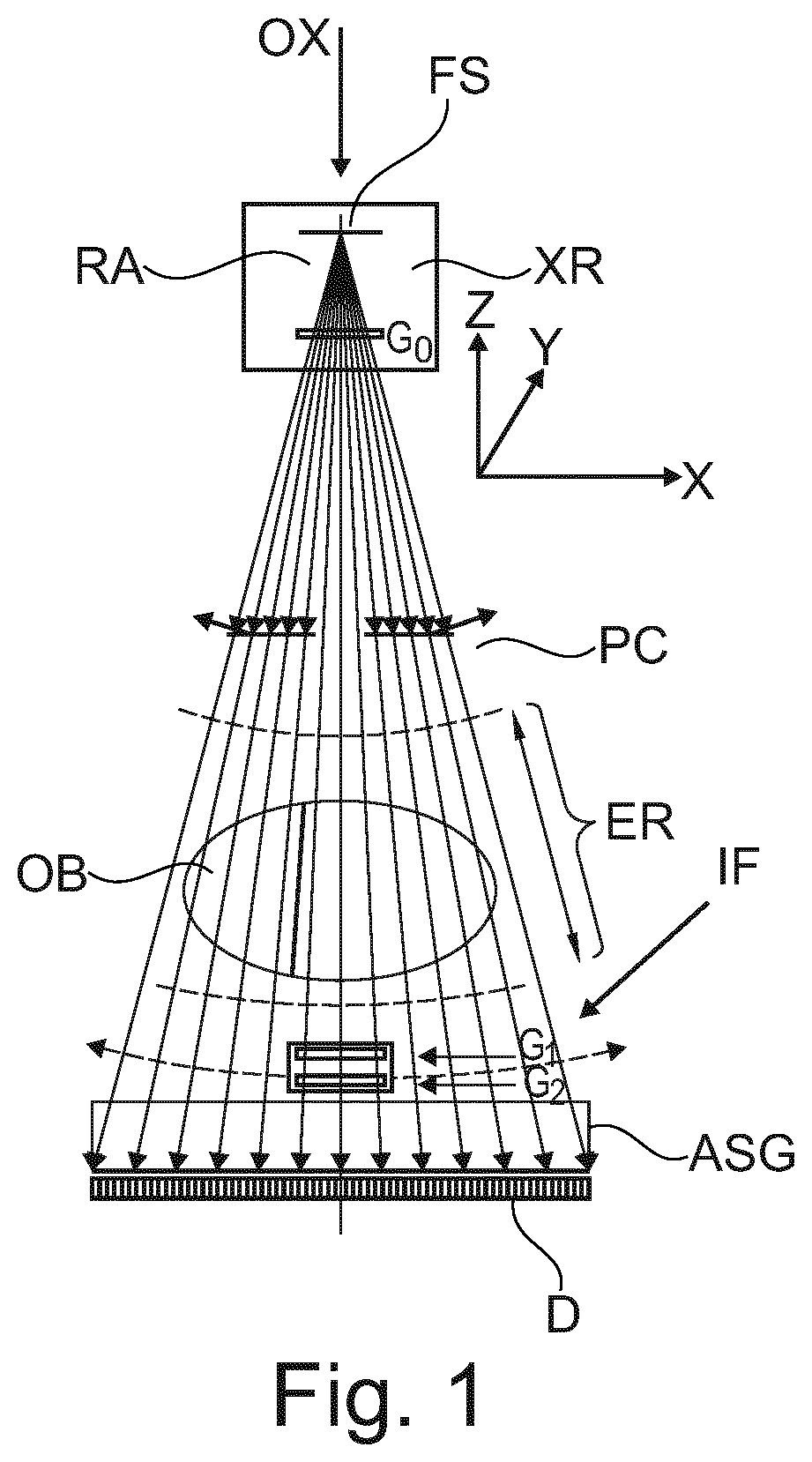
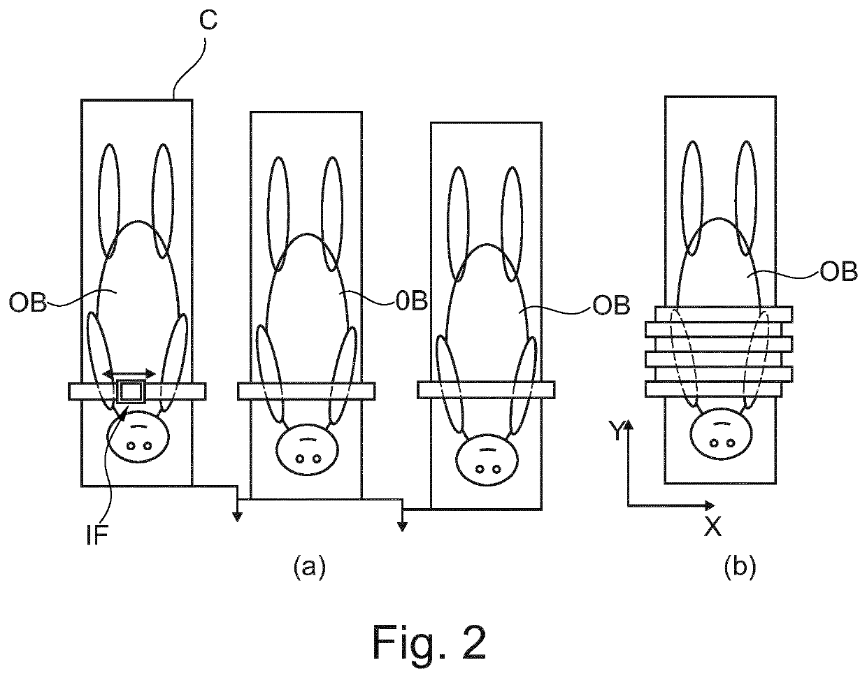
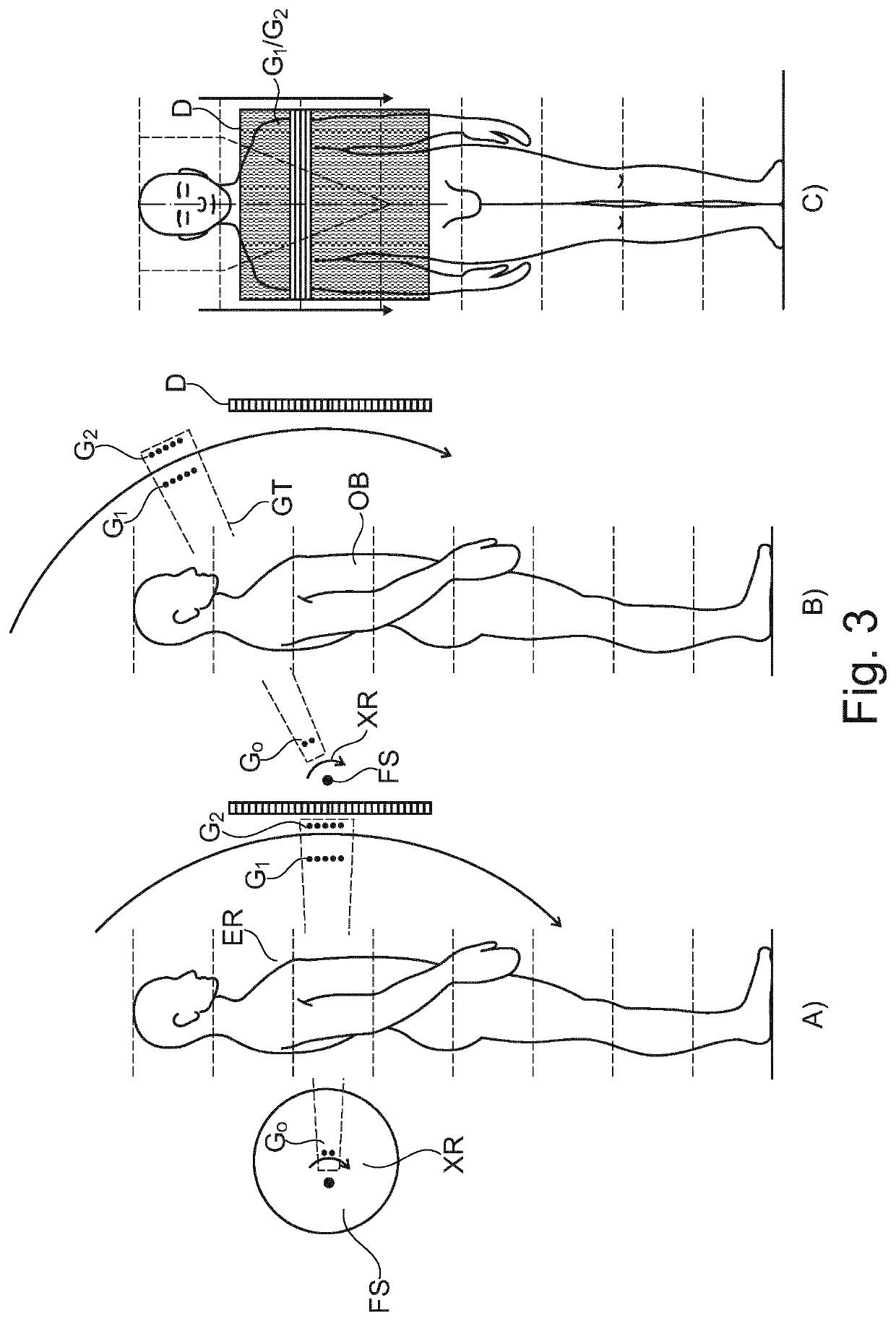
[0032]With reference to the following drawings we propose a new type of X-ray imaging apparatus. The X-ray apparatus is capable of multi-channel imaging, that is, it is not only capable of imaging for spatial distribution of absorption of or in an object OB but also for the spatial distribution of refraction (phase contrast imaging) and / or for the spatial distribution of small angle scattering (dark field imaging). This type of imaging capability is sometimes referred to a DPCI (differential phase contrast imaging), but, again, it is of course not only the phase contrast one can image for but also for images as per the other two channels. Very briefly, the newly proposed X-ray imaging apparatus has a grating based interferometer that is scannable across a stationary X-ray detector.

[0033]Reference is now made to FIG. 1 where an embodiment of the newly proposed imaging apparatus is schematically shown. We will also use FIG. 1 to introduce certain basic imaging components some of which...


PUM


Abstract

An X-ray imaging apparatus with an interferometer (IF) and an X-ray detector (D). A footprint of the X-ray detector (D) is larger than a footprint of the interferometer (IF). The interferometer is moved in scan motion across the detector (D) whilst the detector (D) remains stationary. Preferably the detector is a 2D full field detector.

Description

CROSS-REFERENCE TO PRIOR APPLICATIONS[0001]This application is the U.S. National Phase application under 35 U.S.C. § 371 of International Application No. PCT / EP2016 / 064649, filed on Jun. 24, 2016, which claims the benefit of European Patent Application No. 15174413.3, filed on Jun. 30, 2015. These applications are hereby incorporated by reference herein.FIELD OF THE INVENTION[0002]The invention relates to an X-ray imaging apparatus.BACKGROUND OF THE INVENTION[0003]Grating-based differential-phase contrast imaging and dark field imaging are promising technologies that add diagnostic value in particular in the area of chest imaging since the dark field signal channel is highly sensitive to changes of the micro-structure of lung tissue.[0004]Different systems have been proposed on the past. However some of these systems are still relatively expansive due to the required component performance. For instance, full field systems (see for instance Ewald Roessl, “Clinical boundary conditions...

Claims


Application Information

Patent Timeline
Patent Type & Authority Patents(United States)
IPC IPC(8): G03H5/00A61B6/00
CPCA61B6/484A61B6/4035A61B6/4233A61B6/4291A61B6/502A61B6/4464
Inventor KOEHLER, THOMASMARTENS, GERHARDPROKSA, ROLANDMAACK, HANNS-INGOVAN STEVENDAAL, UDOPFEIFFER, FRANZ JOSEFNOEL, PETER BENJAMIN THEODORVON TEUFFENBACH, MAXIMILIAN
Owner KONINKLJIJKE PHILIPS NV
Why Eureka
Try Eureka