
System for treating an epistaxis

a technology for epistaxis and system, applied in the field of medical devices, can solve the problems of system discomfort, considerable risk of secondary hemorrhage, traumatizing wicks, etc., and achieve the effects of less trauma to the patient, and convenient us

Active Publication Date: 2021-03-16
VYGON SA
View PDF9 Cites 0 Cited by
  • Summary
  • Abstract
  • Description
  • Claims
  • Application Information

AI Technical Summary

Benefits of technology

[0010]One objective of the invention is therefore to propose a system for treating an epistaxis which makes it possible to stop a nasal hemorrhage without risk of secondary hemorrhage at the junction point of the hemostasis by applying a controlled pressure on the walls of a nasal cavity of a patient, and which is further simple to implement while still being more ergonomic and less traumatizing for the patient than the systems of the prior art.
[0016]the compression device comprises an implantation tube, configured to be introduced into the nasal cavity of a patient, said implantation tube having a proximal end, a distal end and a central through passage extending between the proximal end and the distal end, and said compressible member being configured to be housed in the central passage of the implantation tube in the compressed configuration, and a fastener configured to be attached to the envelope and protrude from the proximal end of the implantation tube when the compressible member is housed in the central passage, in order to facilitate the introduction of the compressible member and of the envelope into the implantation tube when the compressible member is in the expanded configuration,
[0018]The envelope is configured to hermetically enclose the compressible member so as to form a sealed enclosure, and the compression device is configured to reduce a pressure in the assembly formed by the compressible member enclosed in the envelope so as to bring the compressible member into its compressed configuration,

Problems solved by technology

However, such wicks are traumatizing upon introduction and withdrawal, despite their possible re-humidification prior to withdrawal.
Moreover, there is a considerable risk of secondary hemorrhage due to the poorly controlled pullout of the wick remaining at the junction point of the hemostasis.
However, these systems are particularly uncomfortable for the patient due to the considerable pressure applied by the balloon so as to stop the hemorrhage, knowing that this pressure is often greater than necessary to guarantee that the balloon adapts to the physiognomy of the nasal cavity of the patient.
Moreover, these systems do not have a rapid hemostatic effect.
Moreover, these systems comprising a balloon are flexible and therefore difficult to introduce and to position with accuracy in a nasal cavity of a patient.
However, such a device does not allow either controlling the pressure exerted on the walls of the nasal cavity or avoiding a secondary hemorrhage at the time of withdrawal of the wick.
It is also noted that the introduction of the wick into the nasal cavity is difficult in that it is not guided by the introducing groove.
However, such a device does not allow either controlling the pressure exerted on the walls of the zone of the body to be blotted, or withdrawing the wick in a controlled and non-traumatic manner.
This system is also not suitable for the introduction of a wick into a nasal cavity.
However, such a device does not allow controlling the pressure exerted on the walls of the passage or withdrawing the wick from the cavity non-traumatically.

Method used


Image

  • System for treating an epistaxis
  • System for treating an epistaxis
  • System for treating an epistaxis

Examples


first embodiment

he Outside of the Compressible Member

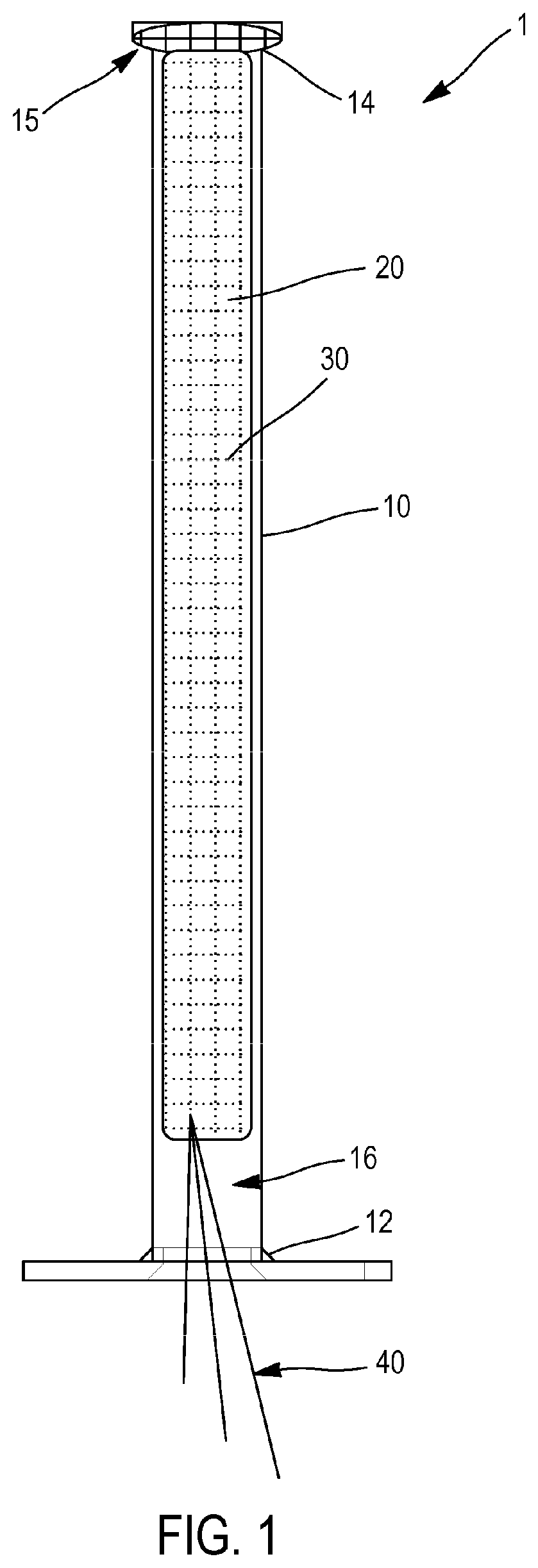
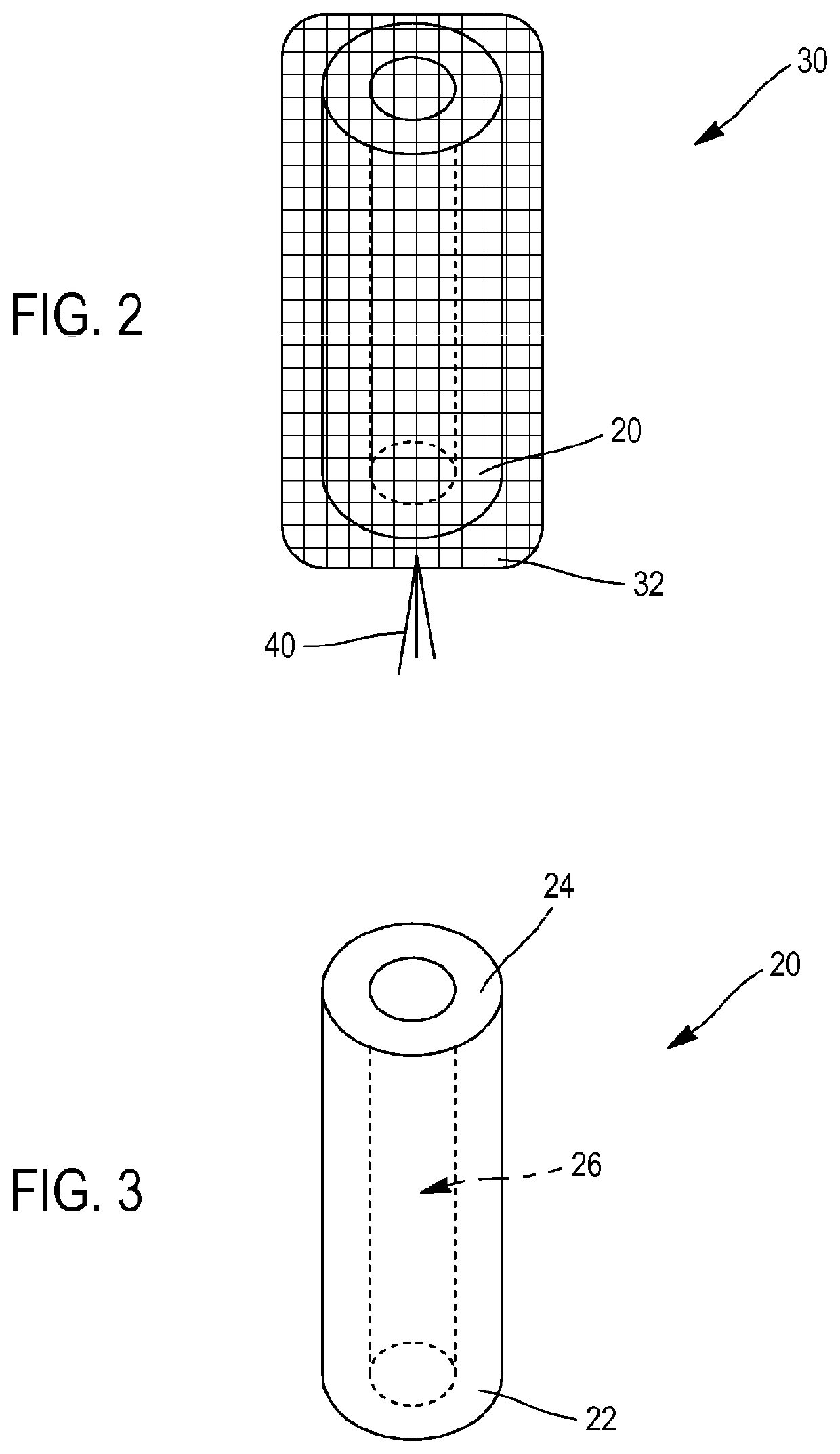
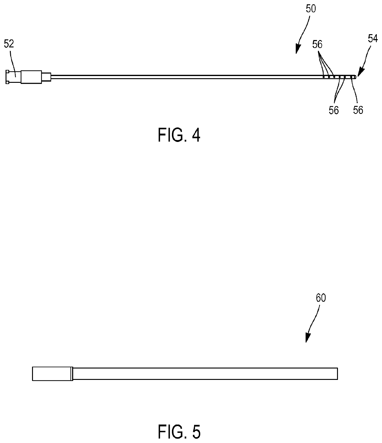
[0072]In this first embodiment, illustrated with reference to FIGS. 1 to 5, the compression device comprises an implantation tube 10, configured to be introduced into the nasal cavity of the patient, said implantation tube 10 having a proximal end 12, a distal end 14 and a central through passage 16 extending between the proximal end 12 and the distal end 14. Moreover, the compressible member 20 has hemostatic properties. Finally, the system further comprises a fastener 40 configured to be attached to the envelope 30 and protrude from the proximal end 12 of the implantation tube 10 when the compressible member 20 is housed in the central passage 16, in order to facilitate the introduction of the compressible member 20 and the envelope 30 into the implantation tube 10 when the compressible member 20 is in the expanded configuration.

[0073]The compressible member 20 can in particular be made of a compressible material with shape memory such as foam,...

second embodiment

the Inside of the Compressible Member

[0134]In this second embodiment, illustrated with reference to FIGS. 6 to 8, the compression device 110 is configured to aspirate air into the compressible member 120. To this end, the compression device 110 can in particular comprise a partial vacuum member, capable for example of reaching a vacuum in the compressible member 120 on the order of 450 mbar. Moreover, the envelope 130 is configured to sealingly enclose the compressible member 120 in order to allow this partial vacuum to be generated.

[0135]The compression device 110 can in particular comprise a syringe, for example a 50 mL syringe when the compressible member 120 has a length L of 10 cm for a diameter D of 2.8 to 2.9 cm.

[0136]As a variant, the compression device 110 could comprise a partial vacuum system 1 conventionally used in hospitals.

[0137]The envelope 130, which is sealed here, must be capable of resisting the pressure difference (with respect to the nasal cavity, which is at a...


PUM


Abstract

The invention relates to a system for treating an epistaxis, comprising: a compressible body designed to come into contact with walls of a nasal cavity of a patient, or surrounded by a veil of hemostatic properties; an envelope designed to envelop the compressible body; and a compression device for compressing the compressible body in the envelope, said compression device being designed so as to compress or release the compressible body.

Description

CROSS REFERENCE TO RELATED APPLICATIONS[0001]The present application is a national phase entry under 35 U.S.C. § 371 of International Application No. PCT / EP2016 / 072419, filed Sep. 21, 2016, published in French, which claims priority from French Patent Application Nos. 1650205 filed Jan. 11, 2016 and 1558872 filed Sep. 21, 2015, all of which are incorporated herein by reference.FIELD OF THE INVENTION[0002]The invention relates to the field of medical devices for controlling a nasal flow or a hemorrhage of the nasal cavities (or epistaxis).TECHNOLOGICAL BACKGROUND[0003]An epistaxis is a flow of blood originating in the nasal cavities. This bleeding is very frequent and benign most of the time. In certain cases, however, it can become, due to its abundance, its repetition or the fragility of the site, a true medical-surgical emergency.[0004]Systems suitable for absorbing the blood and carrying out vasoconstriction by compression against the walls of the nasal cavities have thus been pr...

Claims


Application Information

Patent Timeline
Patent Type & Authority Patents(United States)
IPC IPC(8): A61B17/24A61B17/12A61B17/00
CPCA61B17/24A61B17/1204A61B17/1219A61B17/12104A61B17/12159A61B2017/00849A61B2017/00862A61B2017/00867A61B2017/00893A61B2017/1205A61B2017/246A61B2217/005A61L24/001A61M29/02A61L2400/04A61M2210/0618
Inventor LESTOQUOY, PATRICK
Owner VYGON SA
Learn More