

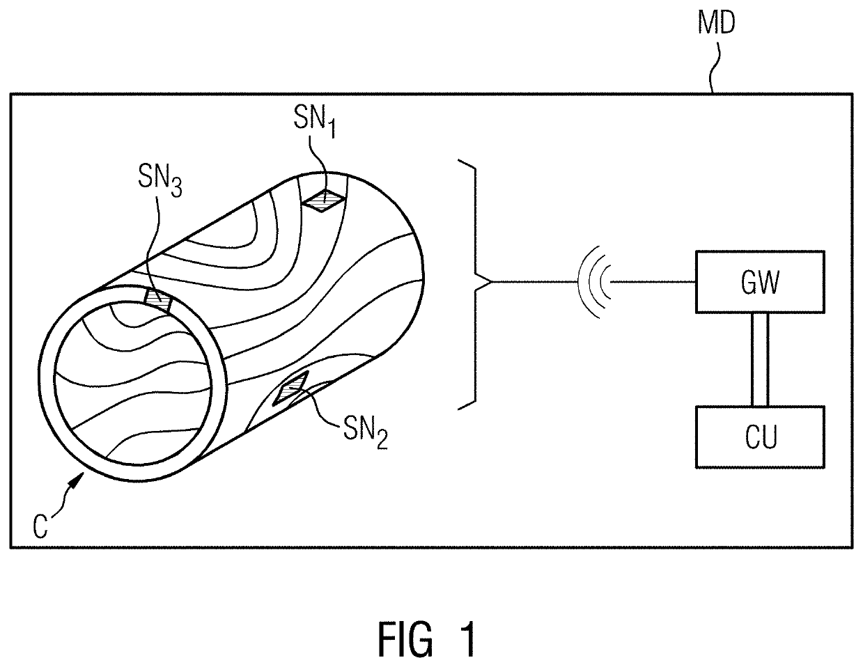
Sensor array in a component of an imaging device
a technology of imaging device and sensor array, which is applied in the direction of magnetic variable regulation, instruments, applications, etc., can solve the problems of high temperature gradient, large mechanical acceleration and centrifugal force of x-ray detector and x-ray generator mounted on the rotating ct gantry, and high mechanical vibration of gradient coil within the mr scanner, so as to avoid signal interference and improve quality
- Summary
- Abstract
- Description
- Claims
- Application Information
AI Technical Summary
Benefits of technology
Problems solved by technology
Method used
Image

Examples
Embodiment Construction
[0059]In the following description, for purposes of explanation and not limitation, specific details are set forth, such as particular network environments and communication standards etc., in order to provide a thorough understanding of the current invention. It will be apparent to one skilled in the art that the current invention may be practiced in other embodiments that depart from these specific details. For example, the skilled person will appreciate that the current invention may be practiced with any wireless network like for example a wireless sensor network (WSN) which may communicate via 6LoWPAN and 802.15.4e standards or an IP-based network. Further, different data communication protocols may be used in this network, depending on the application requirements, including data-centric protocols, like SPIN, Directed Diffusion, Rumor Routing, COUGAR, ACQUIRE, EAD, Information-Directed Routing, Gradient-Based Routing, and location-based protocols, including MECN, SMECN, GAF, G...
PUM
 Abstract
Description
Claims
Application Information