Camera device and method for detecting a surrounding region of a vehicle

Active Publication Date: 2021-03-23
CONTI TEMIC MICROELECTRONIC GMBH
View PDF23 Cites 0 Cited by
  • Summary
  • Abstract
  • Description
  • Claims
  • Application Information

AI Technical Summary

Benefits of technology

[0004]One object of the present invention can therefore be deemed to be to provide a camera device and a method of the type indicated at the outset, which ma

Problems solved by technology

Since, even in the medium term, image-processing, embedded processors will not be able to process the high resolutions of approx.
By contrast, a central unbinned image does not offer a suf

Method used


Image

  • Camera device and method for detecting a surrounding region of a vehicle
  • Camera device and method for detecting a surrounding region of a vehicle

Examples


Example

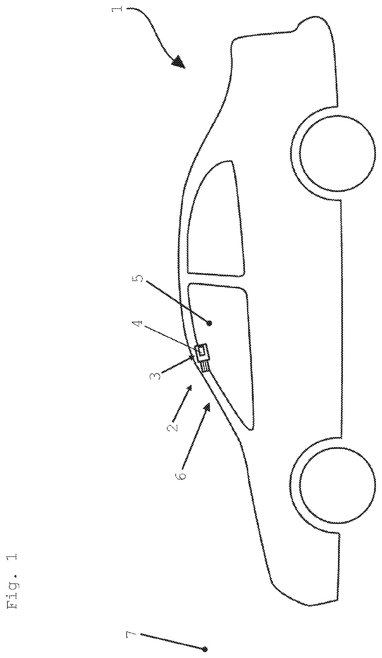
[0039]FIG. 1 shows a vehicle 1 in the form of an automobile. The vehicle 1 comprises a camera device 2 for detecting a surrounding region 7 of the vehicle 1, wherein the camera device 2 in turn comprises an optronic unit 3 having a wide-angle lens and a high-resolution image sensor. Furthermore, the optronic unit 3 can comprise an image processing apparatus 4. If the binning, which is described further below, is performed by an imager, this is implemented in hardware there and can only be parameterized. Software implementation is then not possible in the optronic unit 3, but only in a processor unit which is connected to the imager. In particular, the optronic unit 3 only comprises the lens and the imager. Programs which are run on the processor unit cannot be stored on the optronic unit. This is reserved for the actual processor unit having memory chips attached thereto.

[0040]The camera device 2 is arranged in an interior space 5 of the vehicle 1 and indeed, in particular, in a reg...


PUM


Abstract

A camera device (2) for detecting a surrounding region (7) of a vehicle includes an optronic unit (3) configured to capture an image sequence of the surrounding region. The optronic unit includes a wide-angle lens and a high-resolution image sensor. The optronic unit is configured to reduce the resolution in images in the image sequence, in particular by pixel binning, alternatingly differently and asymmetrically in successive images of the sequence.

Description

FIELD OF THE INVENTION[0001]The invention relates to a camera device and a method for detecting a surrounding region of a vehicle. The invention further relates to the vehicle having such a camera device.BACKGROUND INFORMATION[0002]In order to produce driver assistance devices such as traffic sign recognition or a lane departure warning system, camera systems require a horizontal viewing angle of approx. 50 degrees and a vertical viewing angle of approx. 30 degrees. However, new functions such as cross traffic or traffic light recognition notably require a much larger viewing angle in order to be able to detect objects located in the peripheral area of the image during tailgating. In contrast, highly automated driving or a lane departure warning system, for example, also requires recognition of objects and roadway structures at a great distance, necessitating a corresponding resolution.[0003]Since, even in the medium term, image-processing, embedded processors will not be able to pr...

Claims


Application Information

Patent Timeline
IPC IPC(8): H04N5/232H04N5/225H04N7/18
CPCH04N5/23232H04N5/2253H04N5/2254H04N7/183H04N23/698H04N25/443H04N25/46B60W2420/42H04N25/42H04N23/951H04N23/54H04N23/55
Inventor BREUER, KARSTEN
Owner CONTI TEMIC MICROELECTRONIC GMBH
Why Eureka
Try Eureka