Method for determining an azimuth angle of a wind turbine

a technology of wind turbine and azimuth angle, which is applied in the direction of machines/engines, instruments, mechanical equipment, etc., to achieve the effect of increasing the reliability and/or measurement accuracy of the method

Active Publication Date: 2021-04-06
WOBBEN PROPERTIES GMBH
View PDF21 Cites 0 Cited by
  • Summary
  • Abstract
  • Description
  • Claims
  • Application Information

AI Technical Summary

Benefits of technology

[0008]Even independently of the wind direction correction function, the exact determination of the azimuth angle of the wind power installation is very important, for example during the sectorial curtailment of the wind power installation. For example, the wind power installation can be operated with different operating parameters depending on the sector. If the wind blows from a particular sector, the wind power installation can be operated with reduced sound, for example, in order to shield residents. Furthermore, in a wind farm, the wind power installations positioned upstream can run in a throttled manner depending on the wind direction, as a result of which the turbulence and therefore the installation load are reduced, in particular, in order to allow the wind power installations positioned downstream “to see less turbulence”. A more accurate determination of the azimuth angle therefore entails various advantages.
[0030]The orienting apparatus may be, for example, a laser device. For example, provision may be made for the wind meter to be oriented relative to the nacelle by means of an orienting apparatus which is releasably fastened to the wind meter by means of a holder. It is therefore particularly advantageous if the same holder can be used to attach the at least one GNSS receiver, preferably the at least two GNSS receivers, in particular the position determination apparatus, and / or the telescopic sight to the wind meter, preferably likewise in a releasable manner. This makes it possible, on the one hand, to reuse the holder and, on the other hand, to select a simple fitting which protects the wind meter using this holder.

Problems solved by technology

However, this applies only when the rotor of the wind power installation is not rotating.

Method used


Image

  • Method for determining an azimuth angle of a wind turbine
  • Method for determining an azimuth angle of a wind turbine
  • Method for determining an azimuth angle of a wind turbine

Examples


Embodiment Construction

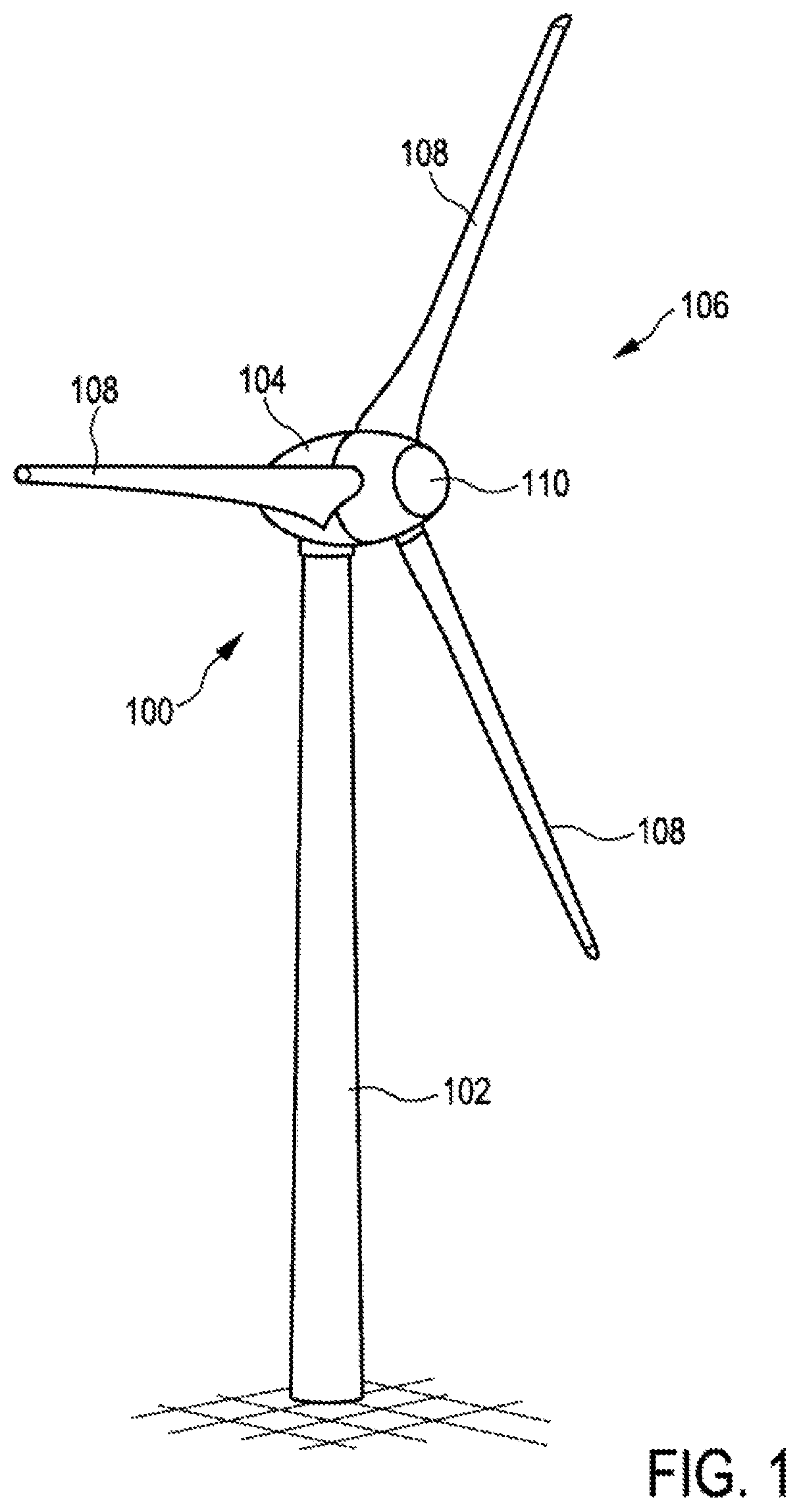
[0053]FIG. 1 shows a wind power installation 100 having a tower 102 and a nacelle 104. A rotor 106 having three rotor blades 108 and a spinner 110 is arranged on the nacelle 104. During operation, the rotor 106 is caused to rotate by the wind and thereby drives a generator in the nacelle 104.

[0054]The compass direction in which the spinner 110 is oriented is referred to as the azimuth angle or viewing direction of the wind power installation 100. So that the nacelle 104 and, with the latter, the rotor 106 are always oriented in the wind direction as much as possible, that is to say the spinner 110 and therefore the installation viewing direction point directly into the wind, a wind measuring supporting frame 160 (see FIG. 11), on which an ultrasonic wind meter 170 (see FIGS. 7 and 11) which is in the form of a combined anemometer and anemoscope and here has four arms 171 is arranged, is usually arranged on the nacelle 104.

[0055]In order to increase the accuracy when determining the ...


PUM


Abstract

A method for determining an azimuth angle of a wind power installation is provided. The method includes attaching at least two global navigation satellite system (GNSS) receivers to a nacelle, comparing reception signals of the GNSS receivers, deriving the azimuth angle from the comparison. The at least two GNSS receivers may be attached to a wind measuring supporting frame. Provided is a method including attaching a telescopic sight to a nacelle, determining a bearing of a bearing object at a bearing angle, deriving the azimuth angle from a comparison of the bearing angle with coordinates of the bearing object and / or the wind power installation. The telescopic sight may be attached to a wind measuring supporting frame. The at least one GNSS receiver may be attached to a wind measuring supporting frame. A wind power installation is also provided.

Description

BACKGROUNDTechnical Field[0001]The invention relates to a method for determining an azimuth angle of a wind power installation. The invention also relates to a wind power installation having a tower, a nacelle and a rotor.Description of the Related Art[0002]In wind power installations, in particular during their installation and commissioning and when sizing prototype constellations, it is important to determine the azimuth angle of the wind power installation. The azimuth angle of a wind power installation is also referred to as the “installation viewing direction” and indicates, in degrees or angles, the compass direction in which the rotor hub or a spinner of the wind power installation points. In order to determine the azimuth angle, a bearing is taken of the wind power installation, usually the rotor hub or the spinner, from a distance using a compass bearing during commissioning of the wind power installation and the azimuth angle is derived therefrom.[0003]In the priority app...

Claims


Application Information

Patent Timeline
Patent Type & Authority Patents(United States)
IPC IPC(8): G01S19/53F03D7/02G01S19/14G01S19/42
CPCG01S19/53F03D7/0212G01S19/14G01S19/42F05B2270/329F05D2270/804Y02E10/72
Inventor WEBER, MARCELJANDL, MARC
Owner WOBBEN PROPERTIES GMBH
Why Eureka
Try Eureka