Apparatus and method for calculating a recording trajectory

a technology of recording trajectory and apparatus, applied in the field of apparatus and method for calculating recording trajectory, can solve the problem of finding the specific optimal trajectory

Active Publication Date: 2021-05-25
FRAUNHOFER GESELLSCHAFT ZUR FOERDERUNG DER ANGEWANDTEN FORSCHUNG EV +1
View PDF7 Cites 0 Cited by
  • Summary
  • Abstract
  • Description
  • Claims
  • Application Information

AI Technical Summary

Benefits of technology

[0012]According to another embodiment, a calculating unit for calculating a recording trajectory of a CT system based on two robots, wherein an X-ray radiation source is arranged on a first robot, whereas the radiation detector is arranged on a second robot, may have: a receive interface for receiving measurement and / or simulation data relative to the object to be recorded; an optimizer configured to determine the recording trajectory based on known degrees of freedom of the CT system with its robots, based on the measurement and / or simulation data and based on a test task from a group having a plurality of test tasks of determining the recording trajectory; and a control unit configured to output data in correspondence with the calculated recording trajectory for controlling a manipulation unit of the CT system and thereby control the CT system in correspondence with the calculated recording trajectory; wherein the positions of the recording trajectory are selected such that a collision between the recording means and the surroundings of the object to be recorded is prevented.
[0016]According to another embodiment, a method for calculating a recording trajectory of a computer tomography system based on two robots, wherein an X-ray radiation source is arranged on a first robot, whereas the radiation detector is arranged on a second robot, may have the steps of: receiving measurement and / or simulation data relative to the object to be recorded; determining the recording trajectory based on known degrees of freedom of the CT system, based on the measurement and / or simulation data and based on a test task from a group having a plurality of test tasks, and outputting data in correspondence with the calculated recording trajectory for controlling a manipulation unit of the computer tomography system in order to control the CT system in correspondence with the calculated recording trajectory; wherein the positions of the recording trajectory are selected such that a collision between the recording means and the surroundings of the object to be recorded is prevented.
[0020]Another embodiment may have a non-transitory digital storage medium having stored thereon a computer program for performing a method for calculating a recording trajectory of a computer tomography system based on two robots, wherein an X-ray radiation source is arranged on a first robot, whereas the radiation detector is arranged on a second robot, having the steps of: receiving measurement and / or simulation data relative to the object to be recorded; determining the recording trajectory based on known degrees of freedom of the CT system, based on the measurement and / or simulation data and based on a test task from a group having a plurality of test tasks, and outputting data in correspondence with the calculated recording trajectory for controlling a manipulation unit of the computer tomography system in order to control the CT system in correspondence with the calculated recording trajectory; wherein the positions of the recording trajectory are selected such that a collision between the recording means and the surroundings of the object to be recorded is prevented, when said computer program is run by a computer.
[0023]This is where the improved concept becomes effective by analyzing, either before or while actually recording, the test object in its basic characteristics in order to detect its geometry, for example, and then determine the trajectory in dependence on the recording mode selected. As a result, the optimizer defines that trajectory (i.e. that succession of position and orientations of the manipulators) where—possibly using the least individual images possible—the result is an image of optimum and, for a task, sufficient quality. The advantage here is that an optimum image quality having a minimum level of x-ray projections and, thus, a very short measuring duration can be achieved. Thus, each measurement is accelerated sufficiently for the respective test task given.
[0026]In correspondence with further embodiments, the recording trajectory may also be selected such that collisions, like with the object or test surroundings, are avoided. This is possible since, when knowing the object, the free space is known sufficiently well, based on the measurement or simulation data established before.

Problems solved by technology

Unusually large and / or complex objects on the one hand and demand for particularly fast measurements on the other hand result in the requirement of obtaining the information used for the test task from considerably fewer transmission images, maybe under restricted accessibility of the test object.
However, the problem resulting is that a specific optimum trajectory has to be found.

Method used


Image

  • Apparatus and method for calculating a recording trajectory
  • Apparatus and method for calculating a recording trajectory
  • Apparatus and method for calculating a recording trajectory

Examples


Embodiment Construction

[0038]Before discussing below embodiments of the present invention in greater detail referring to the appended drawings, it is to be pointed out that elements and structures of equal effect are provided with equal reference numerals so that the description thereof is mutually applicable and interchangeable.

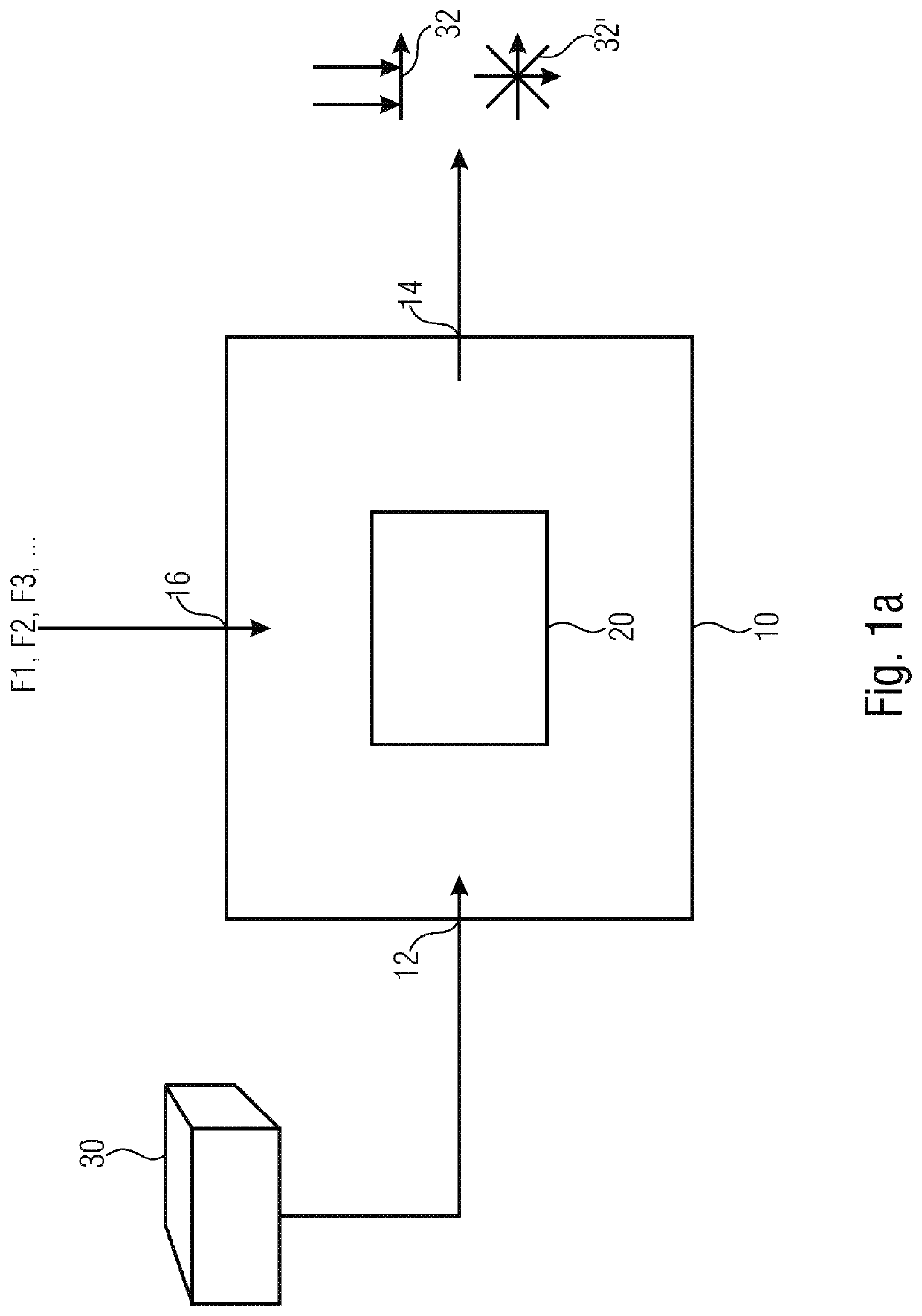
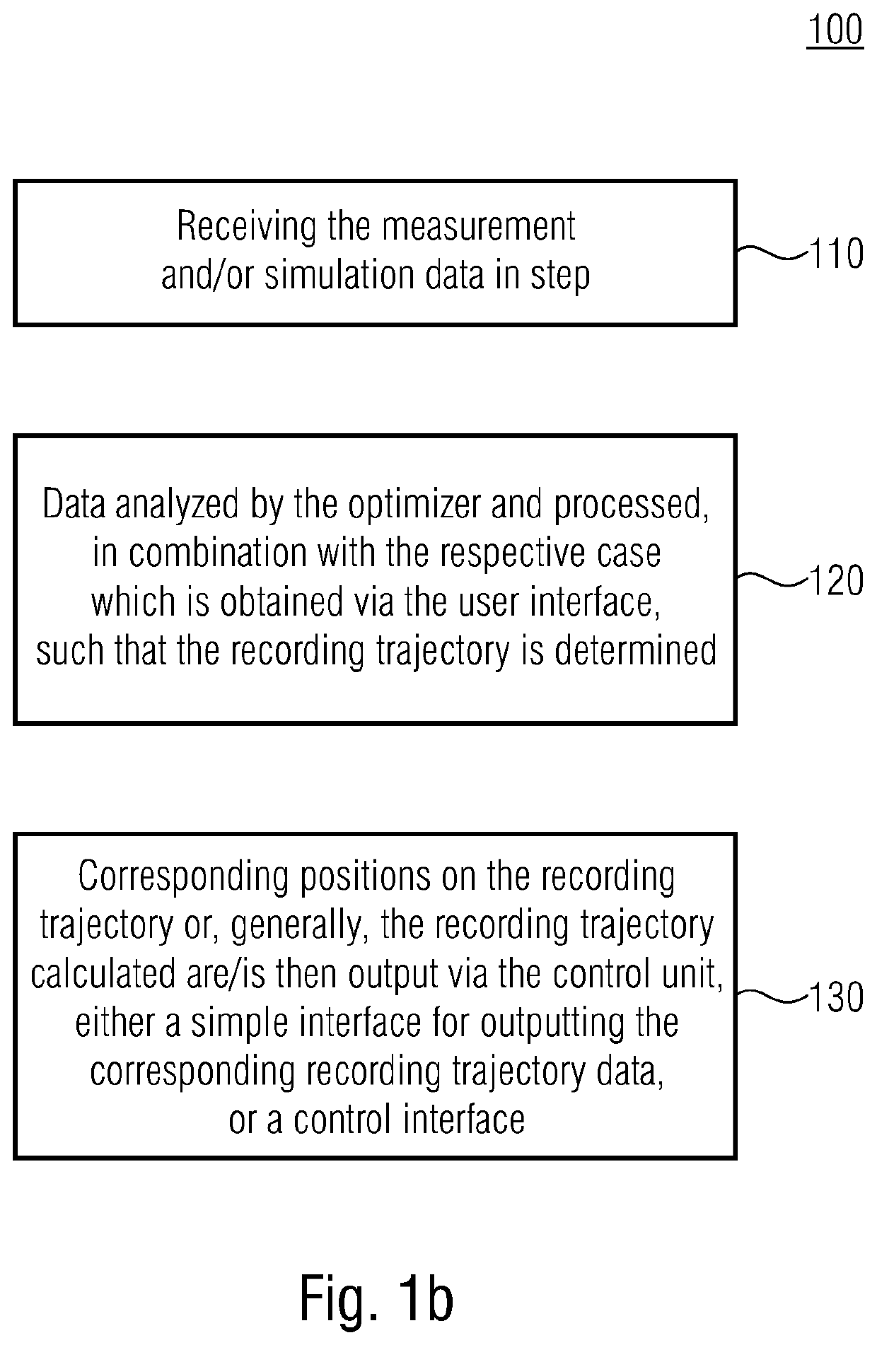
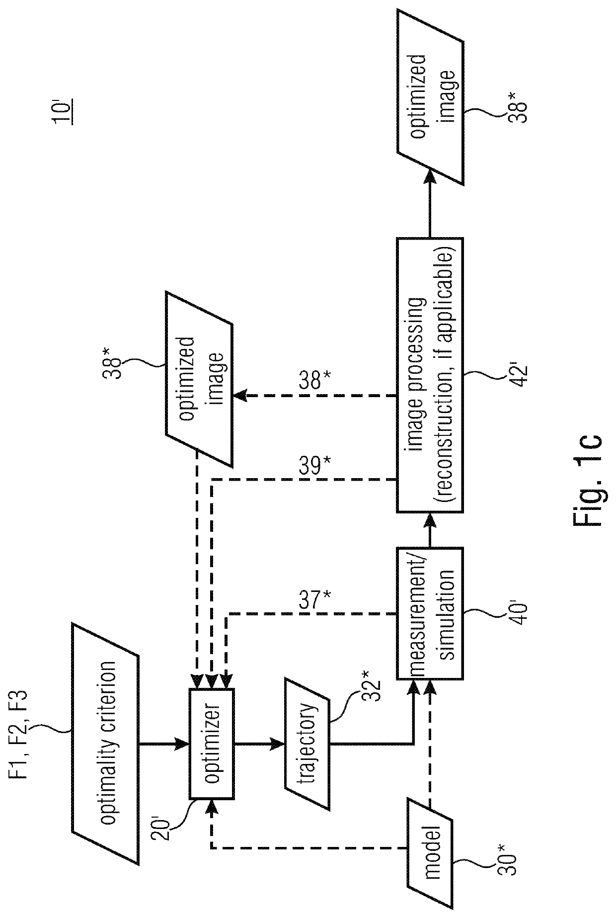
[0039]FIG. 1 shows a calculating unit 10 for calculating a recording trajectory of a CT system. The calculating unit comprises the receive interface 12, the optimizer 20 and a control unit 14. Furthermore, in this embodiment, the calculating unit comprises an interface 16 for receiving a current recording situation (like position / orientation of the object).

[0040]Measurement and / or simulation data relative to the object to be recorded are obtained via the interface 12. In this case, these are simulation data from an x-ray simulation for the recording object 30, wherein the x-ray simulation may, for example, be based on CAD data for the recording object 30. As is illustrated in FIG....


PUM

PropertyMeasurementUnit
transmission angleaaaaaaaaaa
anglesaaaaaaaaaa
recording trajectoryaaaaaaaaaa

Abstract

A calculating unit for calculating a recording trajectory of a CT system has a receive interface, an optimizer and a control unit. The receive interface serves for receiving measurement and simulation data relative to the object to be recorded. The optimizer is configured to determine the recording trajectory based on known degrees of freedom of the CT system, based on the measurement and simulation data and based on a test task from a group having a plurality of test tasks. The control unit is configured to output data in correspondence with the recording trajectory for controlling the CT system.

Description

CROSS-REFERENCE TO RELATED APPLICATIONS[0001]This application is a continuation of copending International Application No. PCT / EP2017 / 068098, filed Jul. 18, 2017, which is incorporated herein by reference in its entirety, and additionally claims priority from German Application No. 10 2016 213 403.5, filed Jul. 21, 2016, which is also incorporated herein by reference in its entirety.BACKGROUND OF THE INVENTION[0002]Embodiments of the present invention relate to an apparatus and to a corresponding method for calculating a recording trajectory of a CT system. Another embodiment relates to a corresponding computer program.[0003]X-ray computer tomography (CT) uses an advantageously full data set of radiographic or transmission images. Advantageously full for such a data set means that the image data processing following after recording separate x-ray transmission images, like reconstruction, can solve a question from a test task in a sufficiently precise manner. A specific succession of...

Claims


Application Information

Patent Timeline
Patent Type & Authority Patents(United States)
IPC IPC(8): G01N23/046G01N23/18G01N23/083
CPCG01N23/046G01N23/18G01N23/083G01N2223/1016G01N2223/306G01N2223/33G01N2223/405G01N2223/41G01N2223/419G01N2223/427G01N2223/606G01N2223/648G01N2223/66
Inventor SCHIELEIN, RICHARDHOLUB, WOLFGANG
Owner FRAUNHOFER GESELLSCHAFT ZUR FOERDERUNG DER ANGEWANDTEN FORSCHUNG EV
Why Eureka
Try Eureka