Pressurized cooling fan and instructions for use

a cooling fan and pressurized technology, applied in the field of cooling fans, can solve problems such as airflow gap between blades, and achieve the effects of reducing production costs, reasonable structural design, and convenient production and processing

Active Publication Date: 2021-06-01
NINGBO SHENGJIU HEAT RADIATION TECH
View PDF4 Cites 1 Cited by
  • Summary
  • Abstract
  • Description
  • Claims
  • Application Information

AI Technical Summary

Benefits of technology

[0003]To overcome the above deficiencies, the object of the present invention is to provide a pressurized cooling fan that is used for a metal cabinet door and instructions for use, in order to solve the poor cooling effect due to poor effect of pressurizing of existing similar products, and the technical issues of inconvenience of production and higher production cost. This object is achieved by the following technical solutions.
[0004]A pressurized cooling fan, wherein the fan frame of this cooling fan is provided with inner blades, the inner blades guard is provided with a motor assembly; wherein the design points of this structure is that the outer diameter of the guard of the inner blades is provided with outer blades smaller than the diameter of inner blades, the airflow enters into the fan frame through the gap between outer blades and inner blades, and is guided out through the hollow hole in the rear of the fan frame, the top plane of inner blades is lower than the frame plane of the fan frame; outer blades and inner blades are integrally connected and relatively rotate when the motor assembly rotates. In this way, the effective intake area of the cooling fan substantially increases, the air volume and static pressure will significantly rise; the outer blades and inner blades are integrated to increase higher air volume and static pressure, that is, to reduce to less power consumption for higher air volume and static pressure, and the original inner blades are shared to reduce the cost by ¼.
[0007]The inner blades are single-rotor blades, outer blades are pressurized blades, the area of outer blades is smaller than that of inner blades. The combination of two different blades and the control over area further increases the effective intake area. The inner blades are 5-blade vanes, and the outer blades are 7-blade vanes. The combination of the two numbers of blades is the best embodiment.
[0008]The top of the inner blades guard has a flat surface, the outer blade guard is provided at the center of the outer blades and is a conical convex blade guard, and blades are provided on the outer diameter bevel of the outer blades guard. The structure further enhances the air intake effect of the effective intake zone through the outer blades structure, that is, to produce a conical spiral intake passage.
[0009]The diameter of the top of the inner blades guard is smaller than that of the rear part of the inner blades guard, namely the guard of inner blades is a bevel. The structure further enhances the air intake effect of the effective intake zone through the inner blades structure.
[0012]The present invention has reasonable structural design, convenience of production and processing, lower production cost, higher air volume, and better static pressure; it can be suitably used for the metal cabinet door as pressurized cooling fan and for the further improvement of similar products.

Problems solved by technology

As a result, when the motor assembly drives inner blades to rotate, there is relative rotation between outer blades and inner blades, and there is airflow gap between blades.

Method used


Image

  • Pressurized cooling fan and instructions for use
  • Pressurized cooling fan and instructions for use

Examples


Embodiment Construction

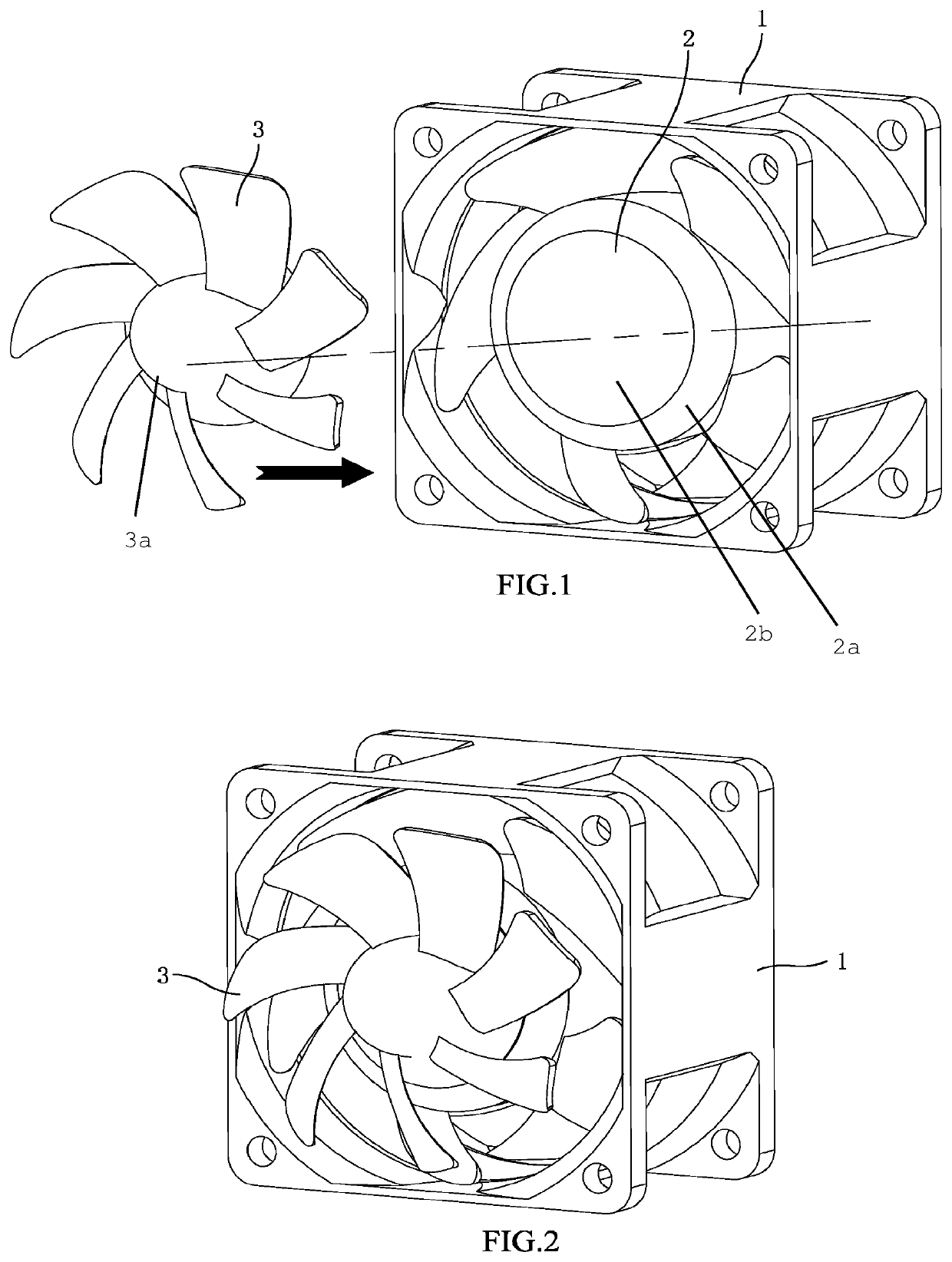
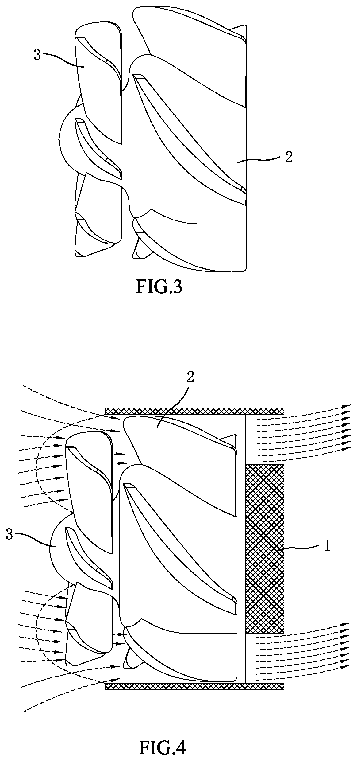
[0017]The structure and use of the present invention is now further described with reference to the attached drawings. As shown in FIG. 1-4, the fan frame 1 of this cooling fan is provided with inner blades 2, a motor assembly is provided in the inner blades guard 2a; in addition, the outer diameter of the top of the inner blades guard 2a is provided with outer blades 3 smaller than the diameter of inner blades 2, inner blades 2 are 5-blade single-rotor vanes, outer blades 3 are 7-blade pressurizing vanes, the area of outer blades 3 is smaller than that of inner blades 2, the top plane of inner blades 2 is lower than the frame plane of the fan frame 1, the top plane of inner blades 2 is lower than that of the frame opening of the fan frame 1. The top of the inner blades guard has a flat surface, the center of outer blades is provided with a outer blades guard 3a that is conical and convex, and the outer blades 3 are provided on the outer diameter bevel of the outer blades guard 3a; ...


PUM


Abstract

A pressurized cooling fan and instructions for use, which is designed specifically to solve poor cooling effect due to poor effect of pressurizing of existing similar products and the technical issues of inconvenience of production, and high production cost. The fan frame of this cooling fan is provided with inner blades, a motor assembly is provided in the guard of inner blades. Airflow enters into the fan frame through the gap between outer blades and inner blades, and is guided out through the hollow hole in the rear of the fan frame, the top plane of inner blades is lower than the frame plane of the fan frame; outer blades and inner blades are integrally connected and relatively rotate when the motor assembly rotates, the air passes through the rear part of the fan frame that is guided by the gap between the fan frame, outer blades and inner blades.

Description

FIELD OF TECHNOLOGY[0001]The present invention relates to a cooling fan or precisely, a pressurized cooling fan and instructions for use.BACKGROUND OF THE INVENTION[0002]The cooling fan generally refers to a fan used for heat dissipation of motherboards such as CPU and graphics card, some cooling fans are also provided with cooling fins with a view to conducting heat and blowing it to the air nearby for cooling purpose. Such cooling fans have been extensively used in metal cabinet doors such as cabinets and electric control cabinets, and generally no cooling fin structure is required. For the single-rotor cooling fans in use, its effective air intake area is narrower, when the static pressure it provides is inadequate, a conventional method is to add double-rotor cooling fan, that is, to add a reverse cooling fan at the outlet side, in order to increase greater static pressure. However, it has very obvious disadvantages, the power consumption of the cooling fan is doubled, so is the...

Claims


Application Information

Patent Timeline
Patent Type & Authority Patents(United States)
IPC IPC(8): F04D19/00F04D25/08F04D29/38
CPCF04D19/007F04D25/08F04D29/384F04D29/325F04D29/646F04D25/0613F04D29/327F04D29/38
Inventor YAO, CHUNLIANG
Owner NINGBO SHENGJIU HEAT RADIATION TECH
Why Eureka
Try Eureka