
Linear actuator for a motor vehicle seat

a technology for motor vehicles and actuators, applied in the direction of vehicle components, vehicle arrangements, machine supports, etc., can solve the problems of requiring no tools and only a small amount of time, and achieve the effect of reducing the risk of injury

Active Publication Date: 2021-06-22
FAURECIA AUTOSITZE
View PDF6 Cites 0 Cited by
  • Summary
  • Abstract
  • Description
  • Claims
  • Application Information

AI Technical Summary

Benefits of technology

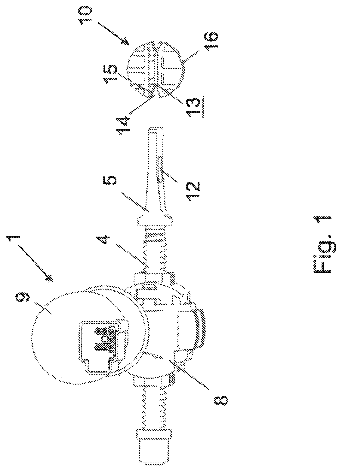
[0008]For installation of the linear actuator in the motor vehicle seat, the linear actuator is inserted in a first orientation into the bearing. Then, the linear actuator is rotated into a second orientation. The fastening means mounted in the bearing forms the center of rotation in this case. The second seat component has a fastening device in which the end of the linear actuator opposite the fastening means is fastened. The installation of the linear actuator in the motor vehicle seat requires no tools and can be executed easily and quickly. The fastening means ideally includes a vibration-damping material—for example, a thermoplastic. Vibrations which occur during the adjustment of the linear actuator are damped by the vibration-damping material of the fastening means. In addition, the fastening means is inexpensive to produce.
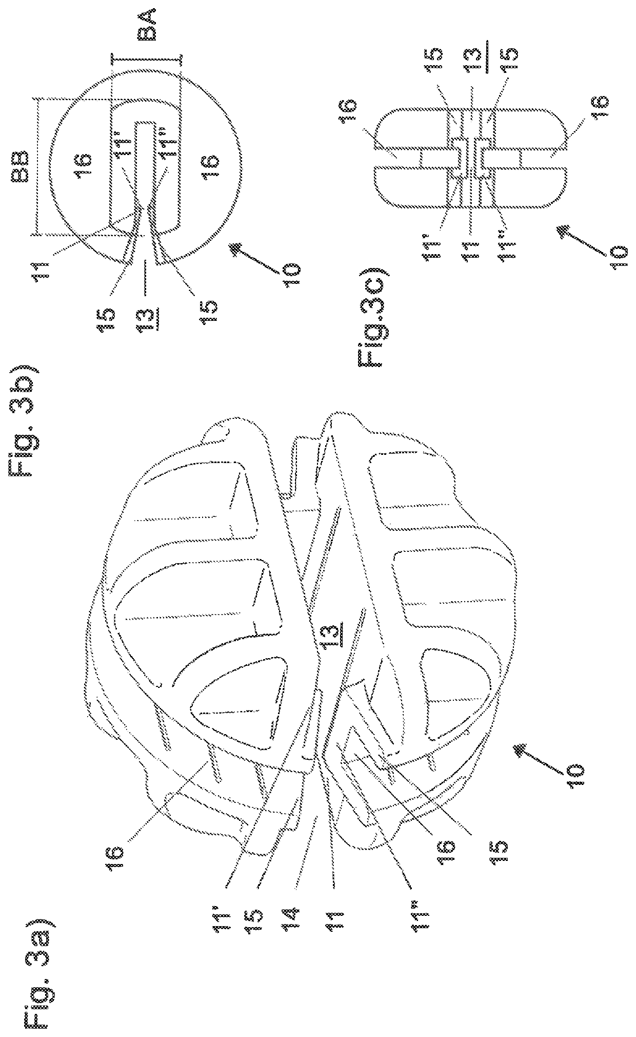
[0012]According to another advantageous feature of the present invention, the opening of the fastening means can be broadened at its entry. The fastening means can be easily connected to the rod head with this design.
[0013]According to another advantageous feature of the present invention, a detent can be arranged in the opening of the fastening means. The detent is part of the clip connection, by means of which the fastening means and rod head can be easily and securely connected to each other.
[0015]According to another advantageous feature of the present invention, the bearing of the first seat component can be annular, and the bearing also has an opening. The fastening means is inserted in a first orientation into the bearing through the opening. The annular design of the bearing allows rotation of the linear actuator into a second orientation.
[0021]According to another advantageous feature of the present invention, the linear actuator can have a motor to drive the engagement means which is engaged with the lead screw. A motor—for example, an electric motor—allows a particularly comfortable linear adjustment of the lead screw in its longitudinal direction, and thus of the motor vehicle seat.

Problems solved by technology

Establishing the connection requires no tools and only a small amount of time.

Method used


Image

  • Linear actuator for a motor vehicle seat
  • Linear actuator for a motor vehicle seat
  • Linear actuator for a motor vehicle seat

Examples


Embodiment Construction

[0035]Throughout all the figures, same or corresponding elements may generally be indicated by same reference numerals. These depicted embodiments are to be understood as illustrative of the invention and not as limiting in any way. It should also be understood that the figures are not necessarily to scale and that the embodiments are sometimes illustrated by graphic symbols, phantom lines, diagrammatic representations and fragmentary views. In certain instances, details which are not necessary for an understanding of the present invention or which render other details difficult to perceive may have been omitted.

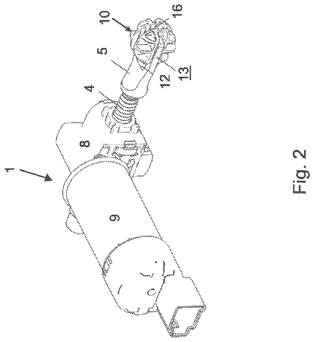
[0036]Turning now to the drawing, and in particular to FIG. 1, there is shown a linear actuator 1 according to the invention (FIG. 1) having a lead screw 4 with a rod head 5, an engagement means 8 which is in engagement with the lead screw 4, and a motor 9. The engagement means 8 is, for example, a worm and is driven by the motor 9, typically a cylindrically shaped electric ...


PUM


Abstract

A linear actuator for adjusting a seat component of a motor vehicle seat includes a lead screw having a rod head. A fastening means is connected to the rod head and connectable to a first seat component of the motor vehicle seat. The first seat component has a bearing, with the fastening means being insertable into the bearing in a first orientation and lockable in the bearing in a second orientation.

Description

CROSS-REFERENCES TO RELATED APPLICATIONS[0001]This application claims the priorities of German Patent Applications, Serial No. 20 2018 102 446.9, filed May 2, 2018, and 10 2019 111 242.7, filed Apr. 30, 2019, pursuant to 35 U.S.C. 119(a)-(d), the disclosures of which are incorporated herein by reference in its entirety as if fully set forth herein.BACKGROUND OF THE INVENTION[0002]The present invention relates to a linear actuator for adjusting a seat component of a motor vehicle seat.[0003]The following discussion of related art is provided to assist the reader in understanding the advantages of the invention, and is not to be construed as an admission that this related art is prior art to this invention.[0004]Adjustable motor vehicle seats allow the user to customize the adjustment of the motor vehicle seat. Accordingly, they provide comfort and safety for the user—for example, by enabling the user to maintain an adequate distance from built-in parts in the frontal region of the mo...

Claims


Application Information

Patent Timeline
Patent Type & Authority Patents(United States)
IPC IPC(8): F16M13/00B60N2/06B60N2/02B60N2/08
CPCB60N2/067B60N2/0232B60N2/08B60N2002/024B60N2/164B60N2/02B60N2/1853B60N2/233B60N2/929B60N2/02253B60N2/02246B60N2/02258
Inventor RÕMER, BERND
Owner FAURECIA AUTOSITZE
Learn More