Quick coupling with multi-piece elastomer seal

a multi-piece, elastomer technology, applied in fluid pressure sealing joints, engine seals, pipe joints, etc., can solve the problems of hydraulic fluid leakage out of the coupling, u-shaped seal or the sickle-shaped seal to fracture, u-shaped seal or the sickle-shaped seal to be ineffective,

Active Publication Date: 2021-06-22
PARKER INTANGIBLES LLC
View PDF26 Cites 1 Cited by
  • Summary
  • Abstract
  • Description
  • Claims
  • Application Information

AI Technical Summary

Benefits of technology

[0009]The present invention provides a novel sealing member and a novel wedging element that may be part of a novel seal assembly. The seal assembly may remain effective for more connection / disconnection cycles as compared to the previously known seals. In exemplary embodiments, the wedging element may engage the sealing member or a pair of the sealing members that sandwich the wedging element. When engaged, an inclined surface of the wedging element may radially compress a radially inwardly extending sealing leg of one or both of the sealing members. A fluid pressure opposite the wedging element relative to the corresponding sealing member may radially expand a radially outwardly extending sealing leg of one or both of the sealing members.
[0010]The sealing member and wedging element may avoid forming high internal pressure pockets when exposed to high fluid pressure, which may reduce or eliminate the risk of the sealing member fracturing when the male coupling is removed after high pressure usage. Reducing the risk of fracturing may allow the lifespan of the sealing member of the present application to be comparatively longer than the previously known C-shaped seals and sickle-shaped seals, which upon exposure to high fluid pressure often form a high internal pressure pocket that may damage the previously known seals when the external pressure is significantly reduced.
[0012]When an external pressure is quickly removed from a previously known U-shaped seal or a previously known sickle-shaped seal, the U-shaped seal or the sickle-shaped seal may quickly expand from the high internal pressure. The quick expansion may cause the U-shaped seal or the sickle-shaped seal to fracture. Fracturing of the U-shaped seal or the sickle-shaped seal may render the U-shaped seal or the sickle-shaped seal ineffective, which can cause hydraulic fluid to leak out of the coupling or allow sea water to leak into the coupling. In contrast, the sealing member of the present application may avoid the quick expansion and reduce the likelihood of fracture.
[0013]When the cylindrical wall of the male portion of a previously known multi-coupling engages the previously known seal with a radially inward facing ridge, the ridge may permanently radially compress after engaging and disengaging the cylindrical wall multiple times. The radial compression may reduce sealing effectiveness of the ridge, which can cause hydraulic fluid to leak out of the coupling or allow sea water to leak into the coupling. In contrast, the sealing member of the present application may axially compress to increase a radial sealing force to prevent reduction of sealing effectiveness.
[0019]According to another aspect of the invention, a sealing member includes a radially outwardly extending sealing leg, a central portion extending axially in a first direction from a radially inner end of the radially outwardly extending sealing leg. Wherein the central portion forms a wedge engaging surface that faces radially outwardly and extends in an inclined manner relative to a longitudinal axis, and a radially inwardly extending sealing leg. Wherein the central portion extends to a radially outer end of the radially inwardly extending sealing leg. Wherein the central portion and the sealing legs circumscribe the longitudinal axis. Wherein the sealing legs are resilient, thereby allowing the sealing legs to resiliently flex relative to the central portion when energized.

Problems solved by technology

The quick expansion may cause the U-shaped seal or the sickle-shaped seal to fracture.
Fracturing of the U-shaped seal or the sickle-shaped seal may render the U-shaped seal or the sickle-shaped seal ineffective, which can cause hydraulic fluid to leak out of the coupling or allow sea water to leak into the coupling.

Method used


Image

  • Quick coupling with multi-piece elastomer seal
  • Quick coupling with multi-piece elastomer seal
  • Quick coupling with multi-piece elastomer seal

Examples


Embodiment Construction

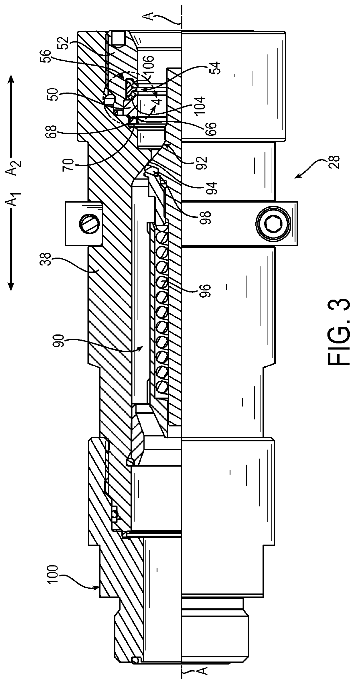
[0030]The principles of this present application have particular application to seal assembly components for female coupling components for hydraulic systems, and thus will be described below chiefly in this context. For example, the female coupling components may connect hydraulic control lines. It will be appreciated that principles of this invention may be applicable to other fluid systems where it is desirable to prevent leakage of fluid.

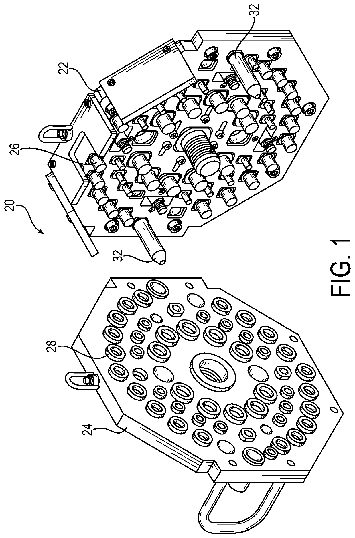
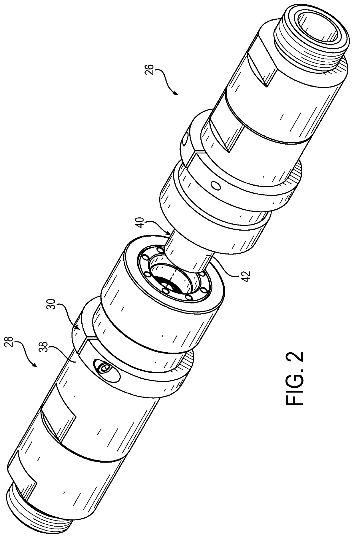
[0031]Referring now to the drawings and initially to FIG. 1, a multi-coupling is designated generally by reference numeral 20. The multi-coupling 20 can be provided, for example, as part of a hydraulic system (not shown) for sub-sea hydraulic applications, such as providing hydraulic fluid to sub-sea oil wells. The multi-coupling 20 may include a fixed plate 22 and a free plate 24 for securing a plurality of male coupling components 26 and a plurality of female coupling components 28, respectively. The female coupling components may include a cl...


PUM


Abstract

A novel sealing member and a novel wedging element that may be part of a novel seal assembly. The seal assembly may remain effective for more connection / disconnection cycles as compared to the previously known seals. In exemplary embodiments, the wedging element may engage the sealing member or a pair of the sealing members that sandwich the wedging element. When engaged, an inclined surface of the wedging element may radially compress a radially inwardly extending sealing leg of one or both of the sealing members. A fluid pressure opposite the wedging element relative to the corresponding sealing member may radially expand a radially outwardly extending sealing leg of one or both of the sealing members.

Description

RELATED APPLICATIONS[0001]This application is a national stage application pursuant to 35 U.S.C. § 371 of PCT / US2017 / 044891 filed on Aug. 1, 2017, which claims the benefit of U.S. Provisional Application No. 62 / 377,182 filed Aug. 19, 2016, which are hereby incorporated herein by reference.FIELD OF INVENTION[0002]The present invention relates generally to fluid seals, and more particularly to multi-piece elastomer seals for quick couplings.BACKGROUND[0003]Quick couplings are devices that allow connection of a single fluid line without a need for special tools. Individual quick couplings typically have a ball locking mechanism to prevent male and female portions of the quick couplings from separating due to internal hydraulic pressure during use.[0004]Multi-couplings typically utilize a group of quick couplings that have male and female portions mounted together in a corresponding plate or casting. Instead of an individual locking mechanism, such as a ball locking mechanism, a larger ...

Claims


Application Information

Patent Timeline
Patent Type & Authority Patents(United States)
IPC IPC(8): F16J15/3232F16J15/3264F16L17/025F16L37/32F16L37/56
CPCF16J15/3232F16J15/3264F16L17/025F16L37/32F16L37/56
Inventor KOLLER, JASON RICHARDFOSE, CARTER
Owner PARKER INTANGIBLES LLC
Why Eureka
Try Eureka