Vehicular panel structure
a technology of panel structure and body, which is applied in the direction of superstructure subunits, vehicle components, doors, etc., can solve the problems of affecting the and reducing the degree of deformation of the body portion toward the panel side. achieve the effect of higher rigidity of the body portion
- Summary
- Abstract
- Description
- Claims
- Application Information
AI Technical Summary
Benefits of technology
Problems solved by technology
Method used
Image
Examples
first embodiment
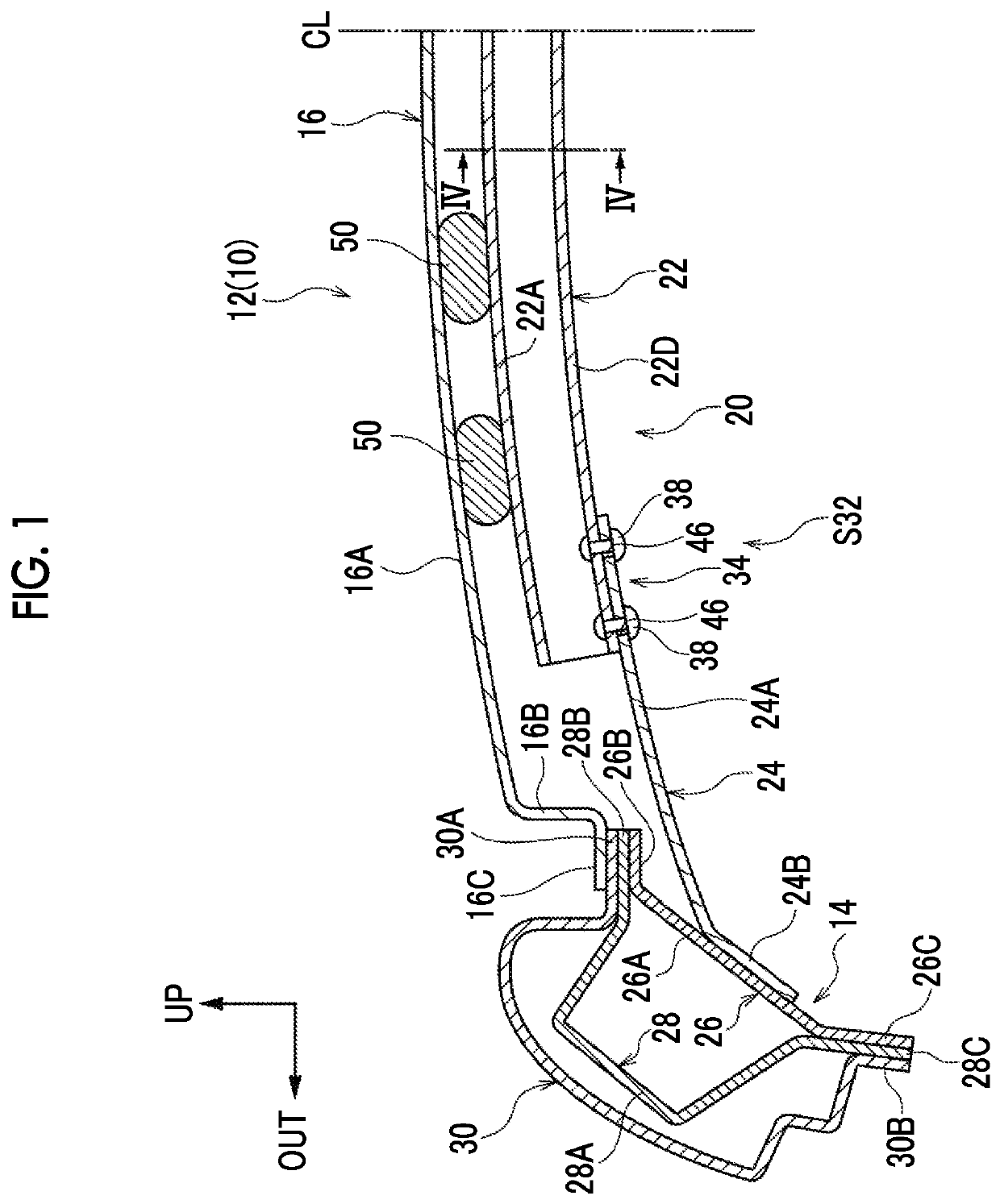
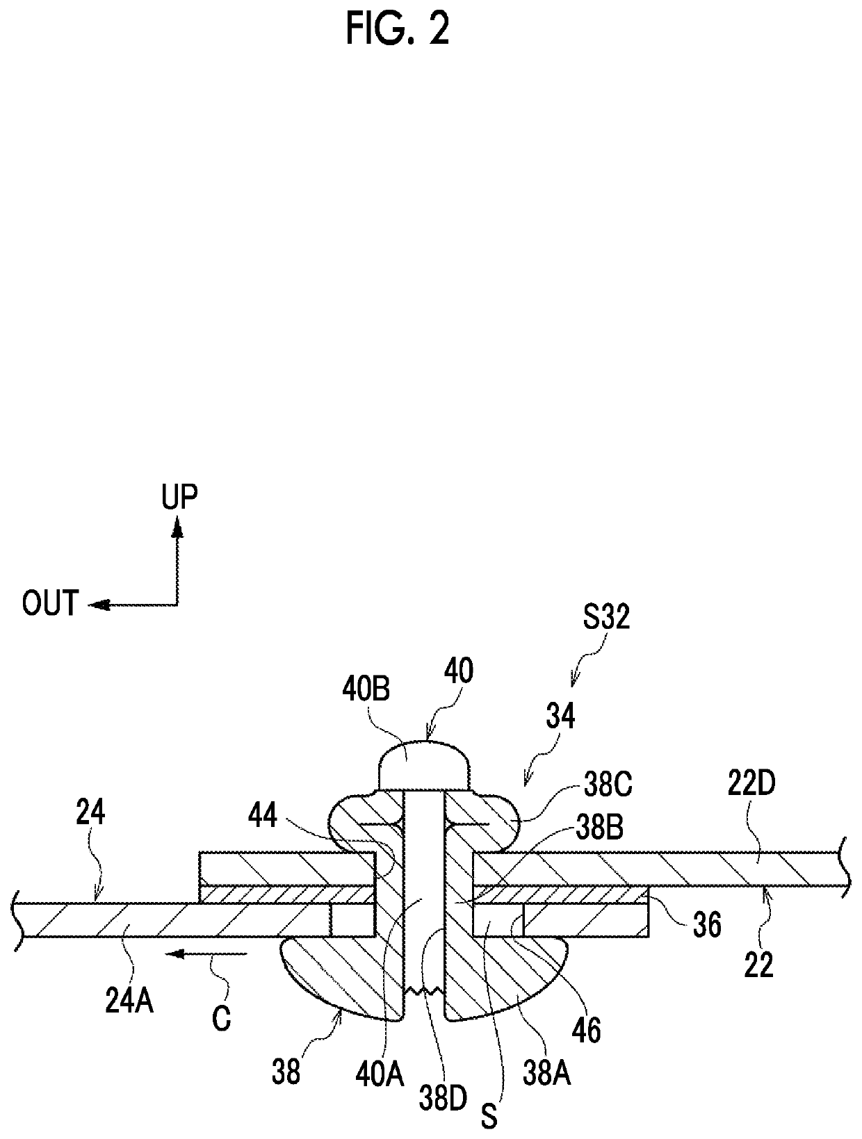
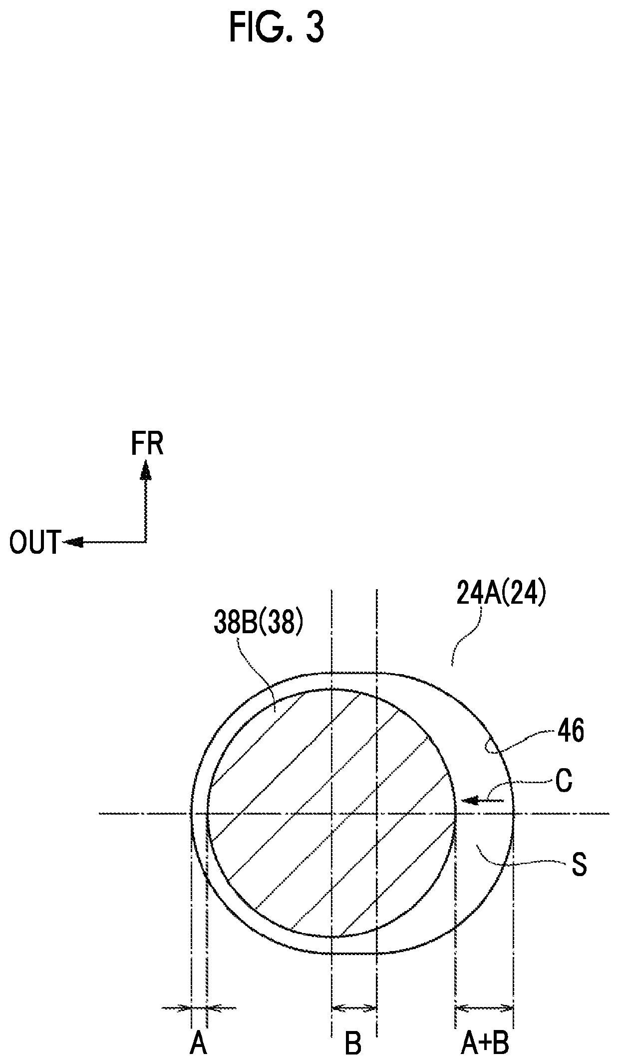
[0031]A vehicular panel structure according to a first embodiment will be described below with reference to FIGS. 1 to 6C.
[0032]FIG. 1 is a sectional view illustrating an upper portion 12 of a vehicle 10 to which a vehicular panel structure S32 according to the first embodiment (refer to FIG. 2) is applied. What is illustrated in FIG. 1 is the part of the upper portion 12 of the vehicle 10 that is on the left side in the width direction of the vehicle when the vehicle is seen from the front of the vehicle. The upper portion 12 of the vehicle 10 is bilaterally symmetrical in the width direction of the vehicle, and the right side in the width direction of the vehicle is not illustrated herein.
[0033]As illustrated in FIG. 1, a roof side rail 14 is disposed in the end portion of the upper portion 12 of the vehicle 10 that is on the outer side in the width direction of the vehicle. The roof side rail 14 extends substantially in the front-rear direction of the vehicle. Although not illust...
second embodiment
[0064]A vehicle door 72 is illustrated in FIGS. 8 and 9 and a vehicular panel structure S70 according to a second embodiment is applied to the vehicle door 72. The same reference numerals will be used to refer to the same components as in the first embodiment described above, and description thereof will be omitted herein.
[0065]As illustrated in FIGS. 8 and 9, the vehicle door 72 is a front side door that is mounted on a side portion of a vehicle (not illustrated) and can be opened and closed. The vehicle door 72 is provided with a door outer panel 74 as a panel (refer to FIG. 9) and a door inner panel 76. The door outer panel 74 is disposed on the outer side in the width direction of the vehicle. The door inner panel 76 is disposed inward of the door outer panel 74 in the width direction of the vehicle. A pair of front and rear terminal portions 76A of the door inner panel 76 on the peripheral edge of the door inner panel 76 that does not include its upper end portion (door glass 7...
third embodiment
[0075]Hereinafter, a vehicular panel structure according to a third embodiment will be described with reference to FIGS. 10 and 11. The same reference numerals will be used to refer to the same components as in the first embodiment described above, and description thereof will be omitted herein.
[0076]The third embodiment is characterized by the materials of the elements of the vehicular panel structure S32 and a specific numerical value (dimension) for the long hole portion 46 being specified.
[0077]According to the first embodiment described above, the roof panel 16 is formed of a steel plate or the like as described above. However, in the third embodiment, a roof panel 16 is formed of an aluminum alloy plate. The linear expansion coefficient of the aluminum alloy plate that is used for the roof panel 16 according to the third embodiment is approximately 23 [10−6 / ° C.].
[0078]A roof reinforcement 22 of a reinforcement 20 is made of carbon fiber reinforced plastic (CFRP) as in the cas...
PUM
 Abstract
Description
Claims
Application Information
 - R&D
- Intellectual Property
- Life Sciences
- Materials
- Tech Scout
- Unparalleled Data Quality
- Higher Quality Content
- 60% Fewer Hallucinations
Browse by: Latest US Patents, China's latest patents, Technical Efficacy Thesaurus, Application Domain, Technology Topic, Popular Technical Reports.
© 2025 PatSnap. All rights reserved.Legal|Privacy policy|Modern Slavery Act Transparency Statement|Sitemap|About US| Contact US: help@patsnap.com


