Method for controlling the outlet temperature of an oil injected compressor or vacuum pump and oil injected compressor or vacuum pump implementing such method

Active Publication Date: 2021-07-27
ATLAS COPCO AIRPOWER NV
View PDF8 Cites 1 Cited by
  • Summary
  • Abstract
  • Description
  • Claims
  • Application Information

AI Technical Summary

Benefits of technology

The present invention aims to provide a method for controlling the outlet temperature of oil injected compressors or vacuum pumps while avoiding condense formation and problems such as instability and oscillation. The goal is to create an energy-efficient and easy-to-implement solution that can be used for existing equipment.

Problems solved by technology

If these systems would allow the outlet temperature to drop below such a limit, condensate would form within the system, which would negatively affect the cooling or lubrication capacity of the oil and would also have a corrosive effect, reducing the life span of the system.
At the same time, the outlet temperature should not be allowed to increase above an upper limit because damages can occur within the system, such as the quality of the oil can be deteriorated or even different components of the system can suffer deformations.
Tests have shown that, when using a fixed temperature thermostat and a fixed speed fan, the implemented solution is not always energy efficient.
Even if the outlet temperature would not significantly exceed the upper limit, the fan would still be started at its fixed and maximum speed, causing the temperature to drop rapidly, typically below the minimum limit, bringing the system in a situation with increased risk of condensate formation.
Tests have shown that such systems can have an erratic and oscillating behavior because the two control loops interfere with one another.
The consequence of such a behavior being the occurrence of emergency shut-downs, damages of the mechanical components and early wear of different system components.
Another drawback of systems using a PID controller is the fact that such a solution is suitable for one input-one output type of analysis, whereas tests have shown that the analysis performed on such systems can be more complex.

Method used


Image

  • Method for controlling the outlet temperature of an oil injected compressor or vacuum pump and oil injected compressor or vacuum pump implementing such method
  • Method for controlling the outlet temperature of an oil injected compressor or vacuum pump and oil injected compressor or vacuum pump implementing such method
  • Method for controlling the outlet temperature of an oil injected compressor or vacuum pump and oil injected compressor or vacuum pump implementing such method

Examples


Embodiment Construction

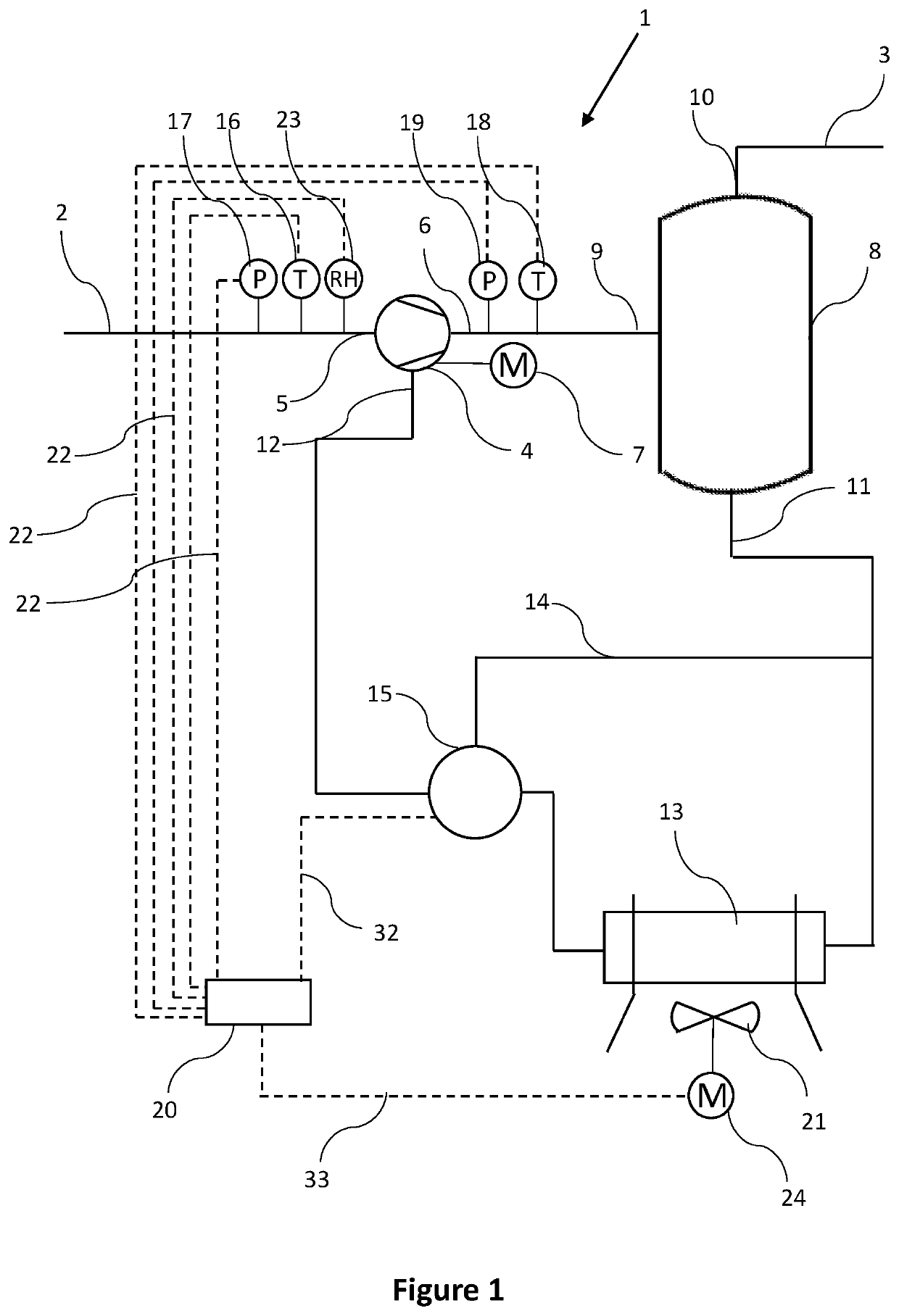
[0057]FIG. 1 illustrates an oil injected compressor or vacuum pump 1 comprising a process gas inlet 2 and an outlet 3.

[0058]The compressor or vacuum pump 1 comprises a compressor or vacuum element 4 having a gas inlet 5 fluidly connected to the process gas inlet 2 and an element outlet 6 fluidly connected to the outlet 3.

[0059]In the context of the present invention the oil injected compressor or vacuum pump 1 should be understood as the complete compressor or vacuum pump installation, including the compressor or vacuum element 4, all the typical connection pipes and valves, the housing of the compressor or vacuum pump 1 and possibly the motor 7 driving the compressor or vacuum element 4.

[0060]In the context of the present invention, the compressor or vacuum element 4 should be understood as the compressor or vacuum element casing in which the compression or vacuum process takes place by means of a rotor or through a reciprocating movement.

[0061]In the context of the present inventi...


PUM


Abstract

The present invention is directed to a method for controlling the outlet temperature of an oil injected compressor or vacuum pump comprising a compressor or vacuum element provided with a gas inlet, an element outlet, and an oil inlet, said method comprising the steps of: measuring the outlet temperature at the element outlet; and controlling the position of a regulating valve in order to regulate the flow of oil flowing through a cooling unit connected to said oil inlet; whereby the step of controlling the position of the regulating valve involves applying a fuzzy logic algorithm on the measured outlet temperature; and in that the method further comprises the step of controlling the speed of a fan cooling the oil flowing through the cooling unit by applying the fuzzy logic algorithm and further based on the position of the regulating valve.

Description

[0001]This invention relates to a method for controlling the outlet temperature of an oil injected compressor or vacuum pump comprising a compressor or vacuum element with a gas inlet, an element outlet, and an oil inlet, said method comprising the steps of: measuring the outlet temperature at the element outlet; and controlling the position of a regulating valve in order to regulate the flow of oil flowing through a cooling unit connected to said oil inlet.BACKGROUND OF THE INVENTION[0002]The need of keeping the temperature at the outlet of an oil injected compressor or vacuum pump to above a minimum limit is known.[0003]Existing systems typically use a fixed temperature thermostat and a fixed speed fan making part of a cooling unit such that when the outlet temperature reaches the minimum limit, the system stops the fan until the outlet temperature increases.[0004]If these systems would allow the outlet temperature to drop below such a limit, condensate would form within the syste...

Claims


Application Information

Patent Timeline
IPC IPC(8): F28F27/00F04B49/06F04C28/00F04B39/06F04D29/00
CPCF04B49/065F04B39/062F04B49/06F04C28/00F04D29/00F28F27/00F04B2205/01F04B2205/02F04B2205/04F04B2205/05F04B2205/10F04B2205/11F05B2210/12F05B2270/303F05B2270/3011F05B2270/3013
Inventor COECKELBERGS, JOERISHI, YUN
Owner ATLAS COPCO AIRPOWER NV
Why Eureka
Try Eureka