Check patentability & draft patents in minutes with Patsnap Eureka AI!

Grid device

a technology of grid devices and grids, applied in the direction of filtration separation, carpet cleaning, separation processes, etc., can solve the problems of reducing utility value, harm or damage, water dirt, etc., and achieve the effect of reducing size and strength

Active Publication Date: 2021-08-10
AVA OF NORWAY AS
View PDF20 Cites 0 Cited by
  • Summary
  • Abstract
  • Description
  • Claims
  • Application Information

AI Technical Summary

Benefits of technology

The grid device effectively keeps the water above cleaner by directing pollutants to the bottom without the need for frequent water changes or continuous clean water supply and reduces energy consumption by minimizing agitation, thus enhancing cleaning efficiency and reducing resource usage.

Problems solved by technology

Particles of a certain size may cause harm or damages if the work system requires usage of homogenous liquid.
It is a commonly understood problem that as dirt and other particulate matter is washed from the surface to be cleaned; it will make the water dirtier.
In a setting where one cleans by usage of used water from a container in such manner that particles are transferred to the water, causing pollution, and motion in the water flow creates a mix of liquid with particles of various sizes with reduced utility value and increased risk of damage.
However, this may be quite resource-demanding concerning working time, effort and water and also supplement in the water e.g. soap, resulting in work inefficiency and strain.
Not only is this a large waste of water, but it is also not a portable solution.

Method used


Image

  • Grid device
  • Grid device
  • Grid device

Examples


Embodiment Construction

[0056]Using the attached drawings, the technical contents, and detailed descriptions, the present invention is described. Alternate embodiments will also be presented.

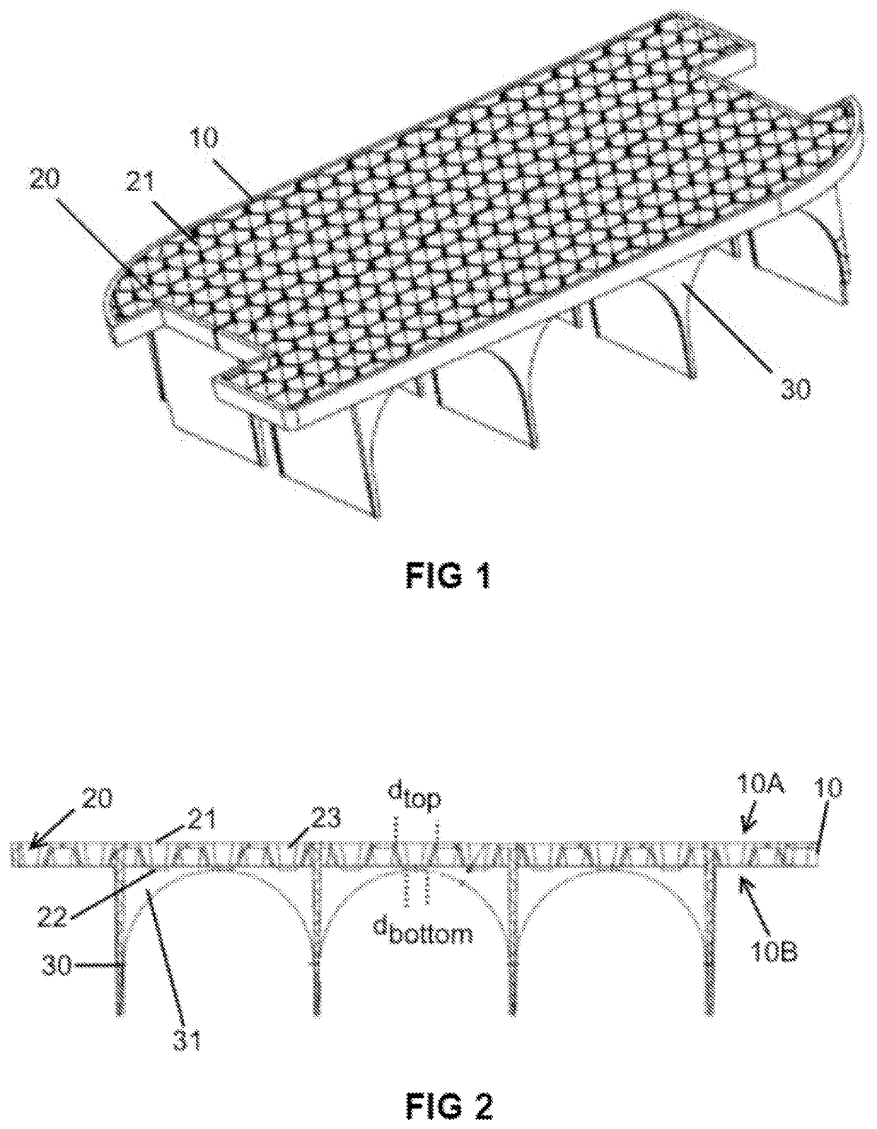
[0057]The present invention is a type of grating. It is meant to be submerged in a container of liquid. The grate is made up of multiple grid elements. One of the key features of these elements is that they have a larger opening on the top than the bottom. This helps in keeping the liquid above the grating cleaner than that below the grating. Further, the grid elements in the grid device will also reduce the currents in the liquid above and below the grid.

[0058]Reference is made to FIG. 1. This figure discloses a perspective view of an embodiment of the present invention. A grate 10 is made up of multiple grid elements 20. A series of supports 30 are affixed to the bottom of the grate 10 at an approximately 90 degree angle to the grate's 10 surface. The purpose of these supports is to allow for the grate to be held in ...


PUM

PropertyMeasurementUnit
thicknessaaaaaaaaaa
degree angleaaaaaaaaaa
widthaaaaaaaaaa

Abstract

The present invention relates to a filtering divider that helps create two regions of liquid cleanliness inside of a container. The liquid on top of the filtering divider will be cleaner than that below the filtering divider. This is achieved using a grate that is comprised of a plurality of grid elements. The filtering divider can optionally be arranged such that it may fold. In such a way, it can be placed in the bottom of a container and provide cavities for the storage of cleaning accessories.

Description

THE FIELD OF THE INVENTION[0001]The present invention relates to a grid device and, more particularly, a grid device adapted to be positioned in a container with a fluid, preferably a liquid. The grid device controls currents in the fluid and facilitates flow of pollutions in the fluid in one direction over the grid. The fluid above the grid device will be cleaner than the fluid below the grid device. Associated devices and systems are also presented.[0002]More specifically, the present invention relates to a grid device comprising a grate with a top surface, a bottom surface, and a plurality of grid elements arranged in a plane along the grate, wherein the grid elements comprise a top opening of a width of dtop in the top surface and a bottom opening of width dbottom in the bottom surface.BACKGROUND AND TECHNICAL PROBLEM TO BE SOLVED[0003]It is very common to wash a dirty surface using a container that is filled with liquid. A ready example of this is the washing of a car using soa...

Claims


Application Information

Patent Timeline
Patent Type & Authority Patents(United States)
IPC IPC(8): A47L13/50D06F3/02A46B17/06B01D29/03A47L23/24B01D29/00
CPCA47L13/50A47L23/24B01D29/0004A46B17/06B01D29/03D06F3/02A47L23/04A47L13/58B01D29/01
Inventor KALAND, TORKILD
Owner AVA OF NORWAY AS
Features
  • R&D
  • Intellectual Property
  • Life Sciences
  • Materials
  • Tech Scout
  • Unparalleled Data Quality
  • Higher Quality Content
  • 60% Fewer Hallucinations
Learn More