Damping valve arrangement

a technology of damping valve and arrangement, which is applied in the direction of spring/damper functional characteristics, functional valve types, shock absorbers, etc., can solve the problem that the precise adjustment of the damping force characteristic at this location cannot be carried out with great difficulty, and achieve the effect of reducing the weight of the force transmission disk and producing particularly inexpensively

Active Publication Date: 2021-08-24
ZF FRIEDRICHSHAFEN AG
View PDF13 Cites 0 Cited by
  • Summary
  • Abstract
  • Description
  • Claims
  • Application Information

AI Technical Summary

Benefits of technology

[0009]In an advantageous manner, the first contact ring and the second contact ring can be formed integral with the force transmission disk. In this regard, the contact rings can be formed at the force transmission disk or formed out of the force transmission disk in a simple manner.
[0011]The force transmission disk could be produced particularly inexpensively from a sheet metal as a bent sheet metal part.
[0012]The force transmission disk can likewise be constructed from a plastic with or without fiber reinforcement, from a thermoset plastic or from a thermoplastic in order to significantly reduce the weight of the force transmission disk in an advantageous manner compared with a force transmission disk constructed from metal (see organic sheets or Organoblech LANXESS®).
[0013]According to a further advantageous constructional embodiment, it can be provided that the first contact ring and / or the second contact ring are constructed in a segmented manner and comprise at least two segments with at least two radial recesses formed between the segments. This further promotes a radially directed flow of the damping fluid.
[0014]Beyond this, it can be provided in an advantageous manner that an axial extension of the first contact ring axially defines a chamber which is arranged between the first spring element and the first surface of the center portion of the force transmission disk. This chamber affords a simple possibility for limiting the maximum deflection height of the first spring element and, accordingly, additionally influencing the damping force characteristic.

Problems solved by technology

Accordingly, a precise adjustment of the damping force characteristic at this location can only be carried out with great difficulty.

Method used


Image

  • Damping valve arrangement
  • Damping valve arrangement
  • Damping valve arrangement

Examples


Embodiment Construction

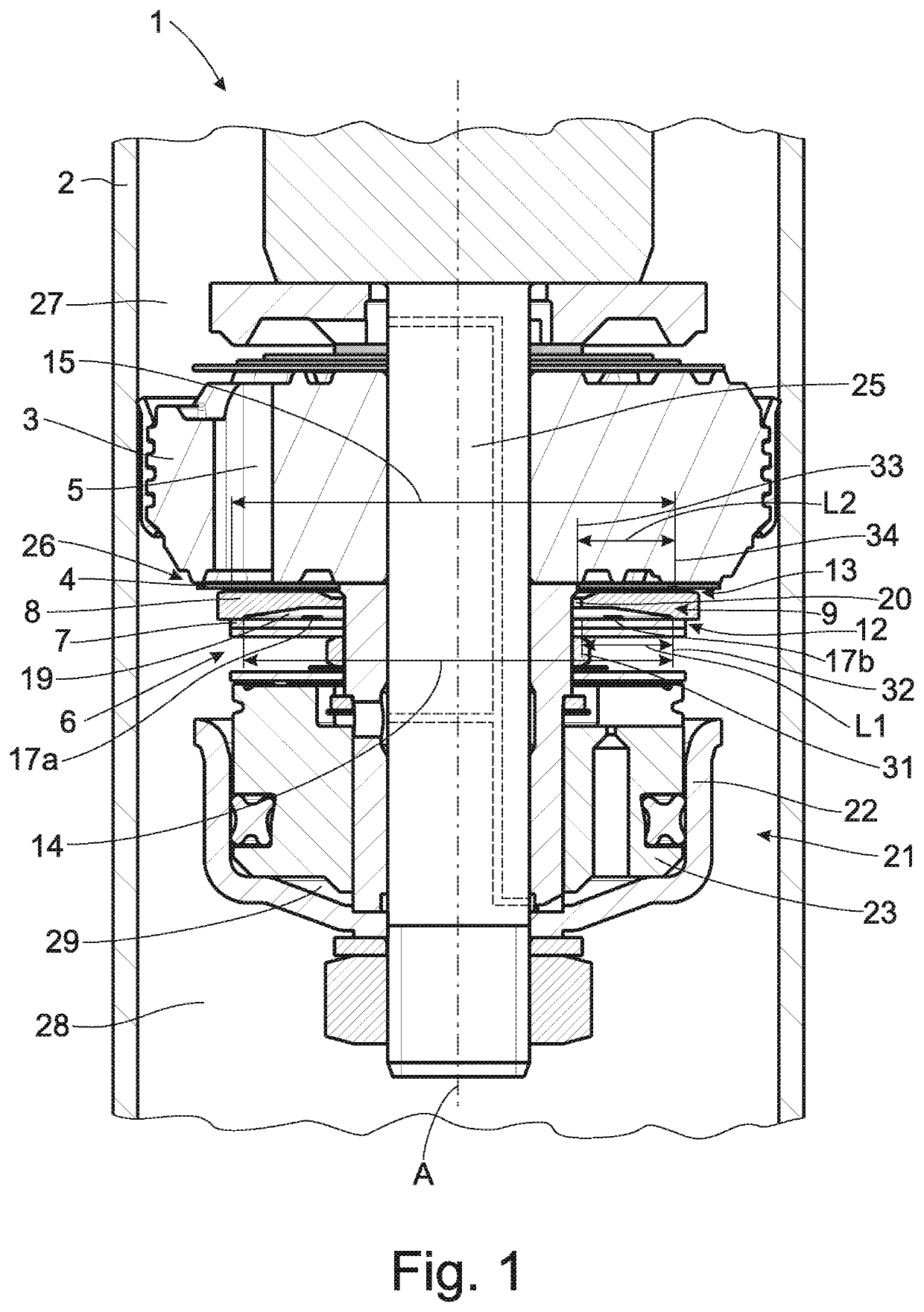
[0025]FIG. 1 is a sectional view showing a portion of a vibration damper for a motor vehicle with a frequency-dependent damping valve arrangement 1 according to the invention.

[0026]The damping valve arrangement 1 is axially displaceably arranged inside of a cylinder 2 which is at least partially filled with a damping fluid, and the damping valve arrangement 1 is fastened to a support 25. The damping valve arrangement 1 comprises a damping valve body 3 with at least one check valve 26 having at least a first throughflow passage 5 for the damping fluid which is formed in the damping valve body 3 and which is covered by at least one valve disk 4.

[0027]Inside of the cylinder 2, the damping valve body 3 divides a first working chamber 27 from a second working chamber 28 such that the ratio of the damping valve pressure in the two working chambers 27, 28 varies depending on the direction of the axial movements of the damping valve body 3 in cylinder 2.

[0028]Beyond this, the damping valve ...


PUM


Abstract

A damping valve arrangement of a vibration damper for a motor vehicle includes a damping valve body having a longitudinal axis A and a throughflow passage is covered by at least one valve disk, a spring arrangement has at least a first substantially disk-shaped spring element; and a force transmission disk arranged between the valve disk and the first spring element so as to be axially displaceable coaxial to the damping valve body. The force transmission disk has a first surface facing the first spring element and comprising a first contact ring with a first diameter, which first contact ring is axially elevated above the first surface, and a second surface opposite the first surface, which second surface faces the valve disk and comprises a second contact ring with a second diameter, which second contact ring is axially elevated above the second surface.

Description

PRIORITY CLAIM[0001]This is a U.S. national stage of application No. PCT / EP2017 / 082116, filed on Dec. 11, 2017. Priority is claimed on the following application: Country: Germany, Application No.: 10 2017 200 375.8, filed: Jan. 11, 2017; the content of which is / are incorporated herein in its entirety by reference.FIELD OF THE INVENTION[0002]The invention is directed to a damping valve arrangement of a vibration damper for a motor vehicle with a damping valve body arranged inside of a cylinder which is at least partially filled with a damping fluid, a spring arrangement which has at least a first substantially disk-shaped spring element, and a transmission disk which receives a spring force from the first spring element of the spring arrangement and transmits it to the valve disk.BACKGROUND OF THE INVENTION[0003]Such damping valve arrangements of a vibration damper for a motor vehicle are amply known.[0004]DE 10 2014 210 705 A1, for example, the content of which is hereby incorporate...

Claims


Application Information

Patent Timeline
Patent Type & Authority Patents(United States)
IPC IPC(8): F16F9/348F16F9/512F16K15/18
CPCF16F9/3488F16F9/5126F16F2228/04F16F2228/08F16F2230/18F16K15/18F16F9/3487
Inventor FÖRSTER, ANDREAS
Owner ZF FRIEDRICHSHAFEN AG
Why Eureka
Try Eureka