Eureka AIR delivers breakthrough ideas for toughest innovation challenges, trusted by R&D personnel around the world.

Systems for capturing a client vehicle

a technology for capturing vehicles and systems, applied in the field of systems, devices, assemblies, apparatus and methods for spacecraft docking, can solve the problems of reducing the reliability of spacecraft, increasing difficulty, and affecting the service life of spacecraft, so as to improve reliability, prevent damage to spacecraft, and simplify the docking architecture

Active Publication Date: 2021-08-31
NORTHROP GRUMMAN SYST CORP
View PDF98 Cites 2 Cited by
  • Summary
  • Abstract
  • Description
  • Claims
  • Application Information

AI Technical Summary

Benefits of technology

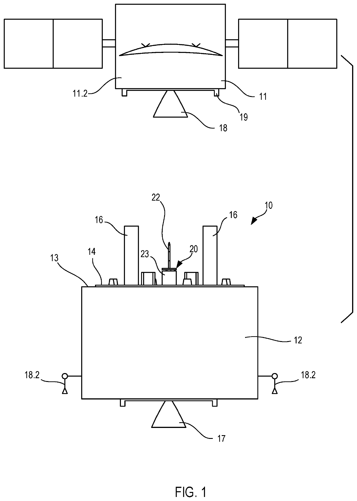
[0007]Some embodiments provide benefits in the form of a relatively simple docking architecture with compliancy for improved reliability and safety, that is, preventing damage to the spacecraft. For example, some embodiments may reduce mechanical complexity of the docking apparatus by utilizing two motors for the docking process. In that embodiment, one motor may be used for extension and retraction of the probe, and another motor may be used for actuation of a finger assembly, reducing points of failure in the capture assembly. Some embodiments utilize a finger assembly design that is actively driven open and closed by a motor, as opposed to spring operated. In some embodiments, the finger assembly may be driven open or closed by a spring assembly.
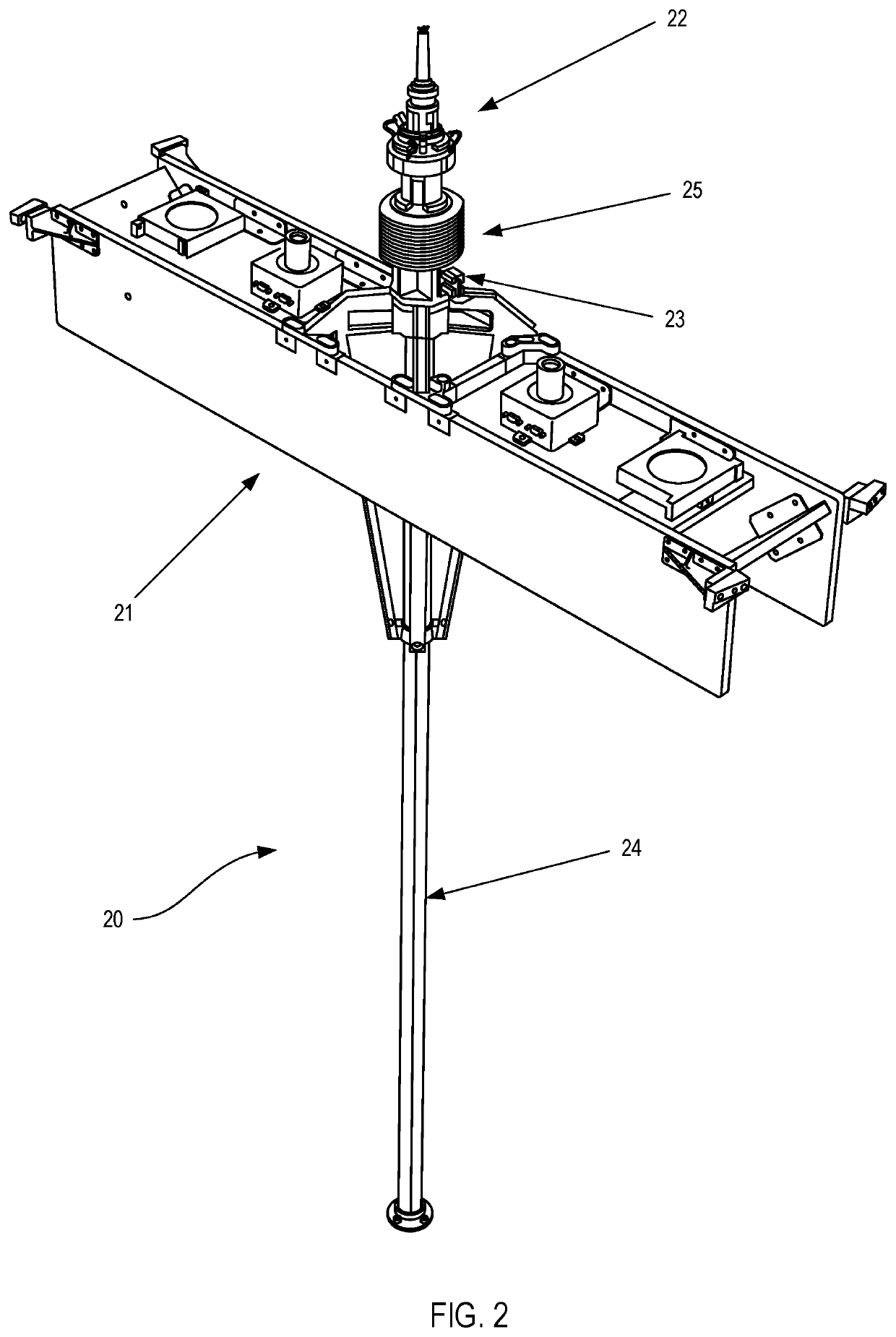
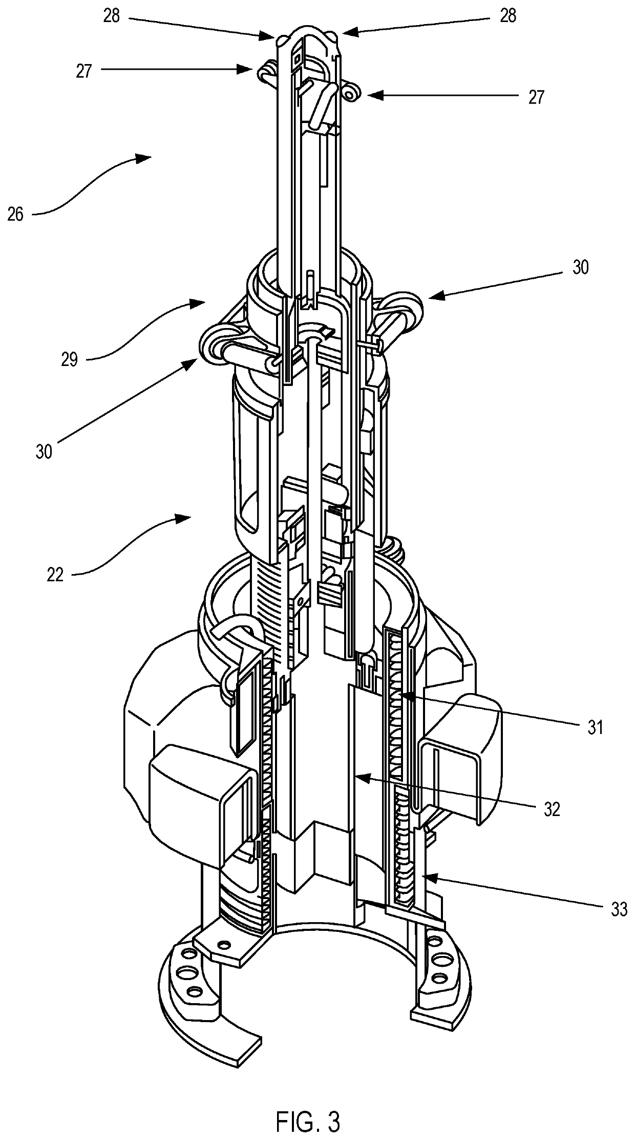
[0008]The finger assembly may include a plurality of fingers disposed at the forward portion of the probe body portion. A first actuator may facilitate configuring the plurality of fingers between an undeployed position, wherein the plurality of fingers are positioned aligned with the probe, and a deployed position, wherein each of the plurality of fingers are rotated about the pivotally connected rearward portion, extending the forward tip outwardly relative to a substantially cylindrical sidewall. In one or more embodiments, the capture assembly includes an extension member at least partially enclosed in a housing. The extension member may be connected to the rearward portion and cooperatively connected to a second actuator for axial movement of the probe. The axial movement of the probe may position the capture assembly between a retracted position, wherein the probe is positioned at least adjacent to the housing, and an extended position, wherein the probe is extended forwardly, relative to the housing.

Problems solved by technology

However, various spacecraft do not have dedicated docking features.
These spacecraft still benefit from servicing, but provide added difficulty due to the lack of dedicated docking features.
Without life extension maintenance, these spacecraft may fall out of service, and replacement is generally extraordinarily expensive and can have a lead time of years.
However, mechanical complexity increases the likelihood of component failure, which can result in failure in the docking and maintenance process.

Method used


Image

  • Systems for capturing a client vehicle
  • Systems for capturing a client vehicle
  • Systems for capturing a client vehicle

Examples


embodiment 1

[0042] A system for capturing a client vehicle in space, the client vehicle having an engine, comprising: a propulsion mechanism for maneuvering the system in space; and a capture mechanism for at least temporarily joining the system to the client vehicle, wherein the capture mechanism includes a probe with a friction reducing element.

[0043]Embodiment 2: The system of Embodiment 1, wherein the engine of the client vehicle is a liquid apogee engine.

[0044]Embodiment 3: The system of Embodiment 1, wherein the friction reducing element is substantially positioned at a distal end of the probe.

[0045]Embodiment 4: The system of Embodiment 3, wherein the friction reducing element is a first item of structural significance at the distal end of the probe.

[0046]Embodiment 5: The system of Embodiment 1, wherein the friction reducing element is one or more rollers.

[0047]Embodiment 6: The system of Embodiment 5, wherein the one or more rollers are dry film lubricated.

[0048]Embodiment 7: The syste...

embodiment 32

[0073] A system for capturing a client vehicle in space, the client vehicle having an engine, comprising: a propulsion mechanism for maneuvering the system in space; a capture mechanism for at least temporarily joining the system to the client vehicle; and a boom for carrying the capture mechanism and movably positioning the capture mechanism relative to the client vehicle.

[0074]Embodiment 33: The system of Embodiment 32, wherein the boom is flexible.

[0075]Embodiment 34: The system of Embodiment 33, wherein the probe is disposed to be actuated into the engine.

[0076]Embodiment 35: The system of Embodiment 34, wherein the boom is sufficiently flexible to reduce friction by reducing normal forces exerted on the client vehicle by the system.

[0077]Embodiment 36: The system of Embodiment 35, wherein the normal forces exerted on the client vehicle are due to misalignment of the probe during actuation into the engine.

[0078]Embodiment 37: The system of Embodiment 36, wherein the normal force...

embodiment 38

[0079] A method for capturing a client vehicle in space using a capture mechanism, the client vehicle having an engine, comprising: maneuvering the capture mechanism into proximity of the engine; providing a friction reducing element on the capture mechanism to reduce friction between the capture mechanism and the engine upon contact of the capture mechanism with the engine; inserting the capture mechanism in the engine; and actuating the capture mechanism to removably join the capture mechanism to the engine.

[0080]Embodiment 39: The method of Embodiment 38, wherein the engine of the client vehicle is a liquid apogee engine.

[0081]Embodiment 40: The method of Embodiment 38, wherein the provided friction reducing element is substantially positioned at a distal end of the capture mechanism.

[0082]Embodiment 41: The method of Embodiment 40, wherein the provided friction reducing element is a first item of structural significance at the distal end of the probe.

[0083]Embodiment 42: The met...


PUM


Abstract

Capture assemblies and compliant extension assemblies may be utilized for insertion into a nozzle of a liquid engine of a spacecraft. The capture assembly may include an apparatus such as a probe for insertion into the nozzle and an assembly at least partially enclosed in a forward portion of the probe. The assembly may include a plurality of actuated fingers for deploying outwardly from the probe when the probe is inserted into the nozzle. The compliant extension assembly may be at least partially enclosed in a housing connected to the capture assembly for axial movement of the probe. The compliant extension assembly may facilitate axial movement of the probe between a retracted position and an extended position, wherein the probe is extended forwardly, relative to the housing.

Description

CROSS-REFERENCE TO RELATED APPLICATION[0001]This application claims the benefit under 35 U.S.C. § 119(e) of U.S. Provisional Patent Application Ser. No. 62 / 484,965, filed Apr. 13, 2017, the disclosure of which is hereby incorporated herein in its entirety by this reference.TECHNICAL FIELD[0002]The present disclosure relates to systems, devices, assemblies, apparatus, and methods for spacecraft docking, and more specifically, to a capture assembly including an apparatus for insertion and capture of an engine of a spacecraft and related methods.BACKGROUND[0003]Thousands of spacecraft orbit the Earth for performing various functions including, for example, telecommunication, GPS navigation, weather forecasting, and mapping. Like all machines, spacecraft periodically require servicing to extend their functioning life span. Servicing may include, for example, component repair, refueling, orbit raising, station-keeping, momentum balancing, or other maintenance. To accomplish this, a servi...

Claims


Application Information

Patent Timeline
Patent Type & Authority Patents(United States)
IPC IPC(8): B64G1/64
CPCB64G1/646B64D39/06B64G1/64B64G1/1078F42B15/36
Inventor SORENSEN, PETER O.MICHEL, MATTHEW ALANLLORENS, WILLIAM A.MURPHY, DAVID M.BRADEN, JEFFREYMCEACHEN, MICHAEL EDWARDFOSTER, MICHAEL
Owner NORTHROP GRUMMAN SYST CORP
Why Eureka
Eureka Blog
Learn More