
Sonar transducer having geometric elements

a technology of geometric elements and sonar transducers, which is applied in the direction of instruments, measurement devices, and using reradiation, can solve the problems of limiting the desirability of the resultant image, and achieve the effects of low detail, reduced structural detail, and high structural detail

Active Publication Date: 2021-08-31
NAVICO HLDG
View PDF40 Cites 0 Cited by
  • Summary
  • Abstract
  • Description
  • Claims
  • Application Information

AI Technical Summary

Benefits of technology

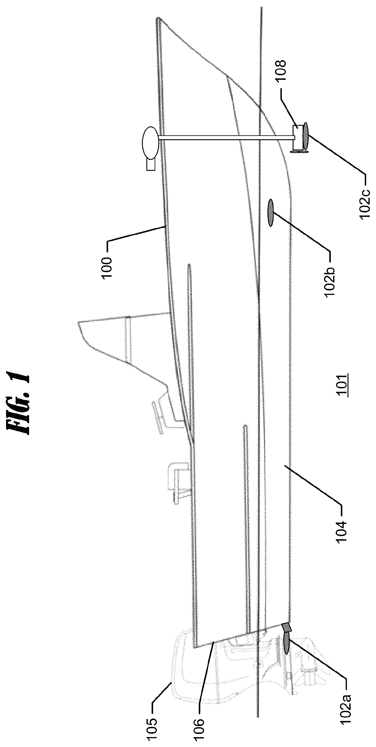
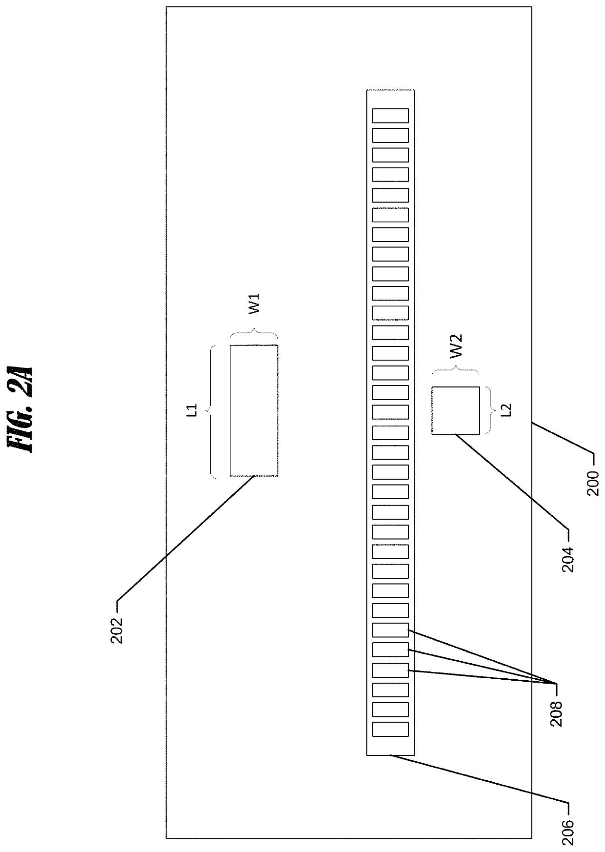
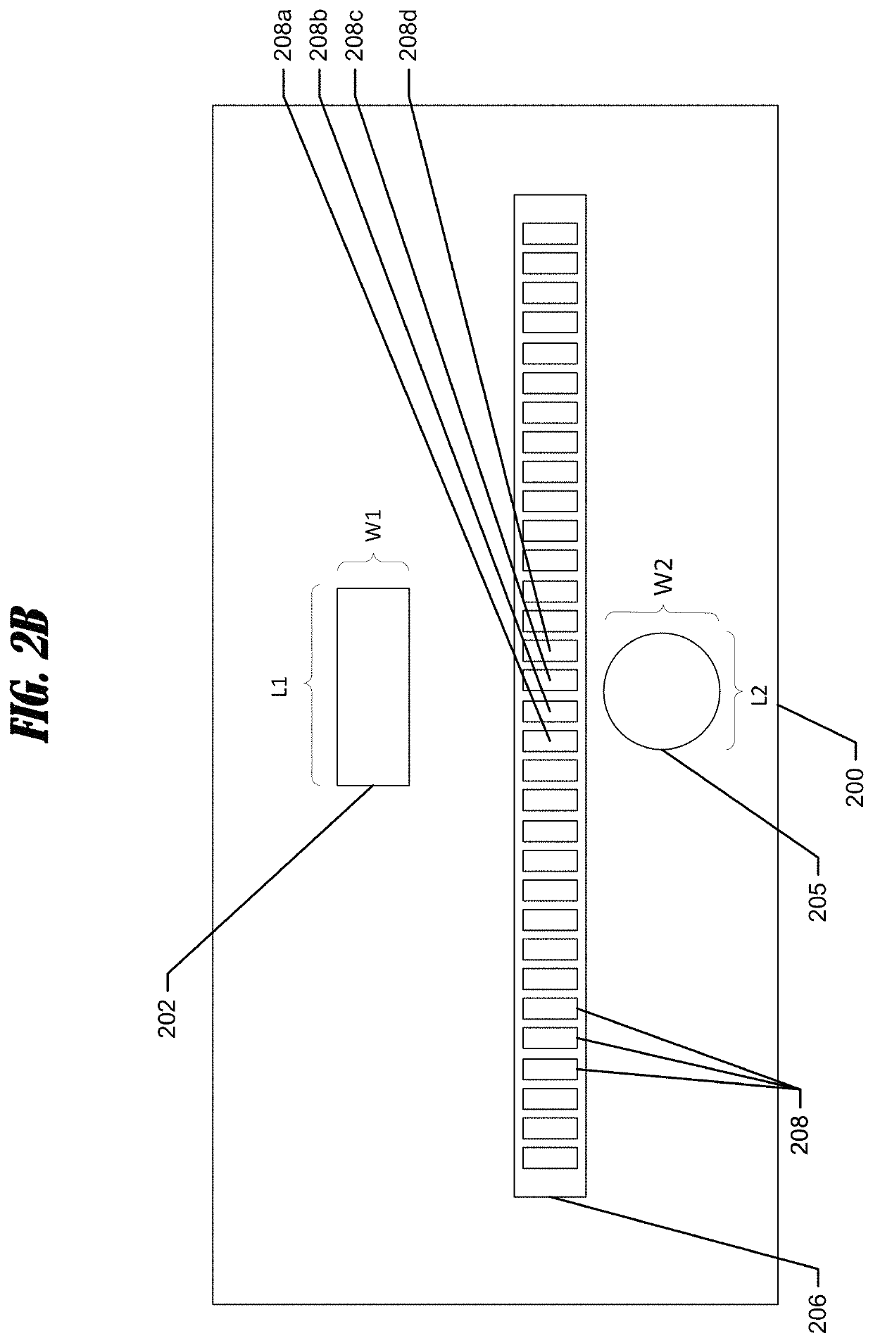
[0005]In some sonar transducer arrangements, a single transducer element may emit one or more sonar signals into the body of water. The resulting sonar returns are then received by one or more second receiving elements and / or the transmitting element. As mentioned above, the shape of the emitting face of the transducer element may determine the shape of the sonar beam emitted therefrom. In applications using an elongated (e.g., linear, elongated rectangle, or the like) transducer element produces a fan-shaped beam, the resulting sonar images may have high structural detail, but relatively low detail for moving objects including fish, bait, or the like. As the length of the emitting face with respect to the width becomes closer to a 1:1 ratio, the shape of the sonar beam shifts from being fan-shaped to a more cone-shape, resulting in reduced structural detail, but an increase in fish detail (e.g., producing desirable “fish arches”). As such, using a single transmitting crystal can limit the resulting image in desirability, such as by producing high structural detail with low fish detail, mediocre structural and fish detail, or high fish detail and low structural detail.
[0010]In some embodiments, an array of series-connected transmit transducer elements can be used to form sonar signal within the water. In this regard, the “effective” emitting face of an array of transducer elements electrically connected in series can determine the resulting beam shape—thereby enabling different types of beam coverage depending on the shapes of the transducer elements and mounting configurations. For example, the orientation of the emitting faces of each element in the array may slightly vary to mimic a curved surface, which may provide for increased beam coverage. In this regard, in some embodiments, the effective curved surface for the emitting face of the array may cause a widened beam coverage in the corresponding direction of the resultant beam—which may be desirable.

Problems solved by technology

As such, using a single transmitting crystal can limit the resulting image in desirability, such as by producing high structural detail with low fish detail, mediocre structural and fish detail, or high fish detail and low structural detail.

Method used


Image

  • Sonar transducer having geometric elements
  • Sonar transducer having geometric elements
  • Sonar transducer having geometric elements

Examples


example architecture

[0107]FIG. 6 shows a block diagram of computing device, such as user device 403. The depicted computing device is an example marine electronic device 405. The marine electronic device 405 may include a number of different modules or components, each of which may comprise any device or means embodied in either hardware, software, or a combination of hardware and software configured to perform one or more corresponding functions. The marine electronic device may also be in communication with a network 402.

[0108]The marine electronic device 405 may also include one or more communications modules configured to communicate with one another in any of a number of different manners including, for example, via a network. In this regard, the communications module may include any of a number of different communication backbones or frameworks including, for example, Ethernet, the NMEA 2000 framework, GPS, cellular, WiFi, or other suitable networks. The network may also support other data source...


PUM


Abstract

A system is provided for imaging an underwater environment. The system includes a transducer assembly with at least one transmit transducer element and an array of receive transducer elements. Each receive transducer element is configured to receive sonar returns and form sonar return data. A sonar signal processor is configured to receive the sonar return data from each receive transducer element and generate sonar image data. The sonar return data from all of the receive transducer elements may be summed and used to form a high-definition 1D (e.g., time-based) sonar image. The sonar return data from only a subgroup may be summed and used to form a lower-definition 1D sonar image. In some systems, an array of series-connected transmit transducer elements can be used. The orientation of the emitting faces of the array may vary slightly to mimic a curved surface for increased beam coverage.

Description

CROSS-REFERENCE TO RELATED APPLICATION(S)[0001]This application claims priority to and is a continuation-in-part of U.S. application Ser. No. 15 / 907,733, entitled “Sonar Transducer Having Geometric Elements”, filed Feb. 28, 2018, which is hereby incorporated by reference in its entirety.FIELD OF THE INVENTION[0002]Embodiments of the present invention relate generally to sonar transducer operation, and more particularly, to systems and apparatuses for sonar transducer operation utilizing geometric transducer elements.BACKGROUND OF THE INVENTION[0003]Sonar (SOund Navigation And Ranging) has long been used to detect waterborne or underwater objects. For example, sonar devices may be used to determine depth and bottom topography, detect fish, locate wreckage, etc. In this regard, due to the extreme limits to visibility underwater, sonar is typically the most accurate way to locate objects underwater. Sonar transducer elements, or simply transducers, convert electrical energy into sound ...

Claims


Application Information

Patent Timeline
Patent Type & Authority Patents(United States)
IPC IPC(8): G01S15/89G01S7/521G10K11/00
CPCG01S15/8995G01S7/521G01S15/8902G01S15/8918G01S15/8993G10K11/008G01S15/89G01S15/87
Inventor ANTAO, BARRYPROCTOR, ALANCASPALL, JAYME
Owner NAVICO HLDG
Learn More