
System and method for an improved personal vaporization device

a technology of personal vaporizer and vaporizer body, which is applied in the direction of digital data authentication, inhalator, other medical devices, etc., can solve the problems of no control as to the vapor metering, no control, no control to prevent the use of the vape device by anyone other than the user of the vape device, etc., to prevent the effect of overheating

Active Publication Date: 2021-08-31
CANOPY GROWTH CORP
View PDF22 Cites 6 Cited by
  • Summary
  • Abstract
  • Description
  • Claims
  • Application Information

AI Technical Summary

Benefits of technology

This patent describes a vape device that can be controlled by an app running on a personal computing device to improve the flavor and amount of vapor produced when inhaling fluid or oil. The device can also prevent overheating and produce vapor that can be seen when exhaled by the user. Additionally, the device avoids stale smoke by quickly cooling down and provides a fast path for vapor to be inhaled. The patent also mentions that the device can be used with high quality oil products that cannot leak from the device.

Problems solved by technology

Conventional vape devices such as these provide: no control as to the ramping up and / or down of power applied to the heating element; no control as to the metering of how much vapor is produced when the switch is closed; no control as to how particular fluids or oils are to be heated to produce vapor; and no control to prevent unauthorized use of the vape device by anyone other than the user of the vape device.

Method used


Image

  • System and method for an improved personal vaporization device
  • System and method for an improved personal vaporization device
  • System and method for an improved personal vaporization device

Examples


first embodiment

of Vape Device

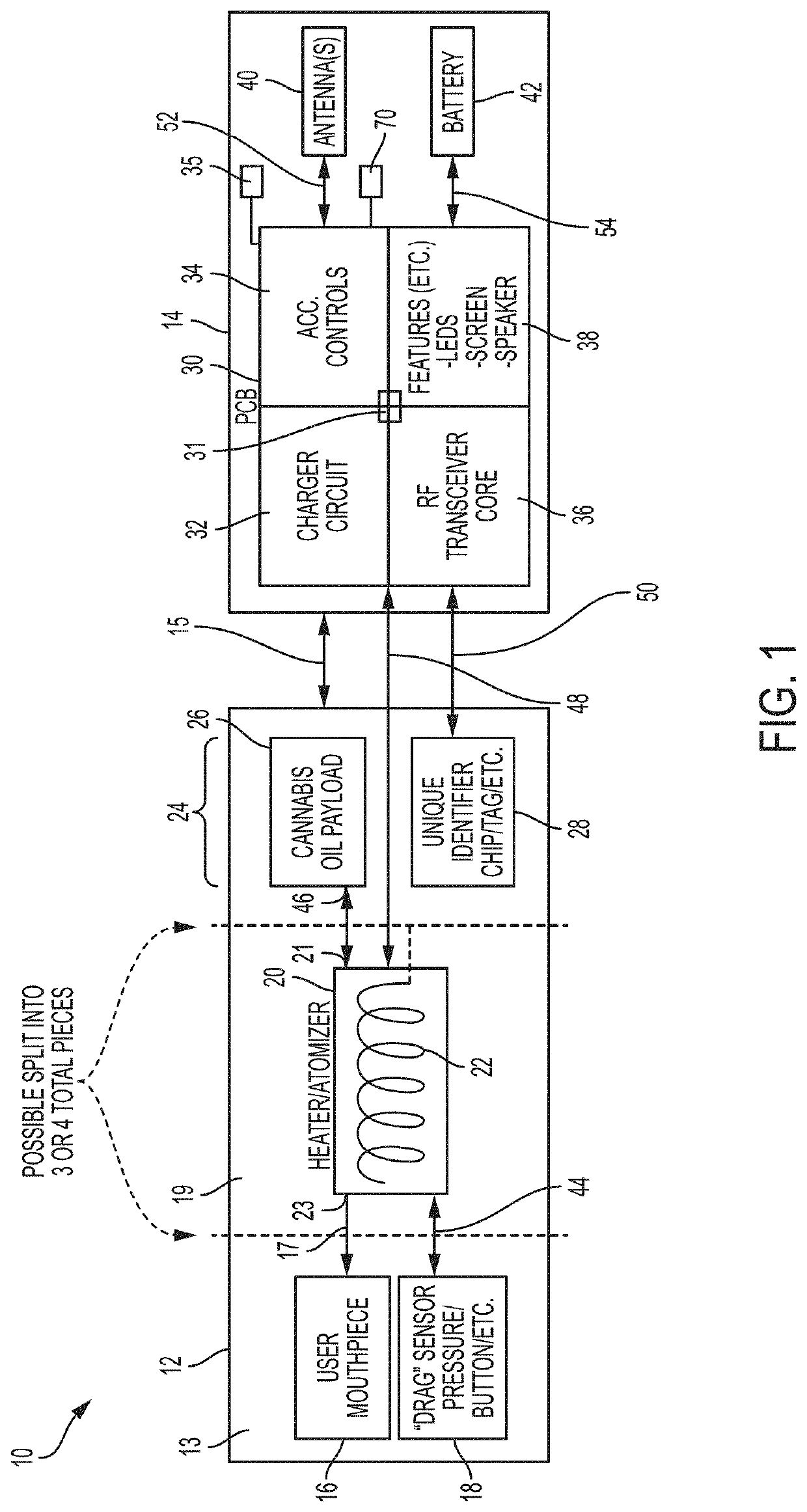
[0065]Referring to FIG. 1, one embodiment of vape device 10 is shown. Vape device 10 includes a mouthpiece assembly 12, an atomizer assembly 19, a payload assembly 24, and a control assembly 14. Any of mouthpiece assembly 12, atomizer assembly 19, payload assembly 24, and control assembly 14 may be formed integrally together and included within a common housing suitable for grasping by a user. Further, any of mouthpiece assembly 12, atomizer assembly 19, payload assembly 24, and control assembly 14 may be formed in separate housings that are releasably connected to each other via connecting means 15, which can comprise, for example, one or more of pressure or friction fit connection means, twist mechanical lock means, magnetic connection means and any other connecting means as well known to those skilled in the art. The connecting means 15 may include a female 510 threaded connector on the control assembly 14 that releasably engages a male 510 threaded connector on the...

second embodiment

of Vape Device

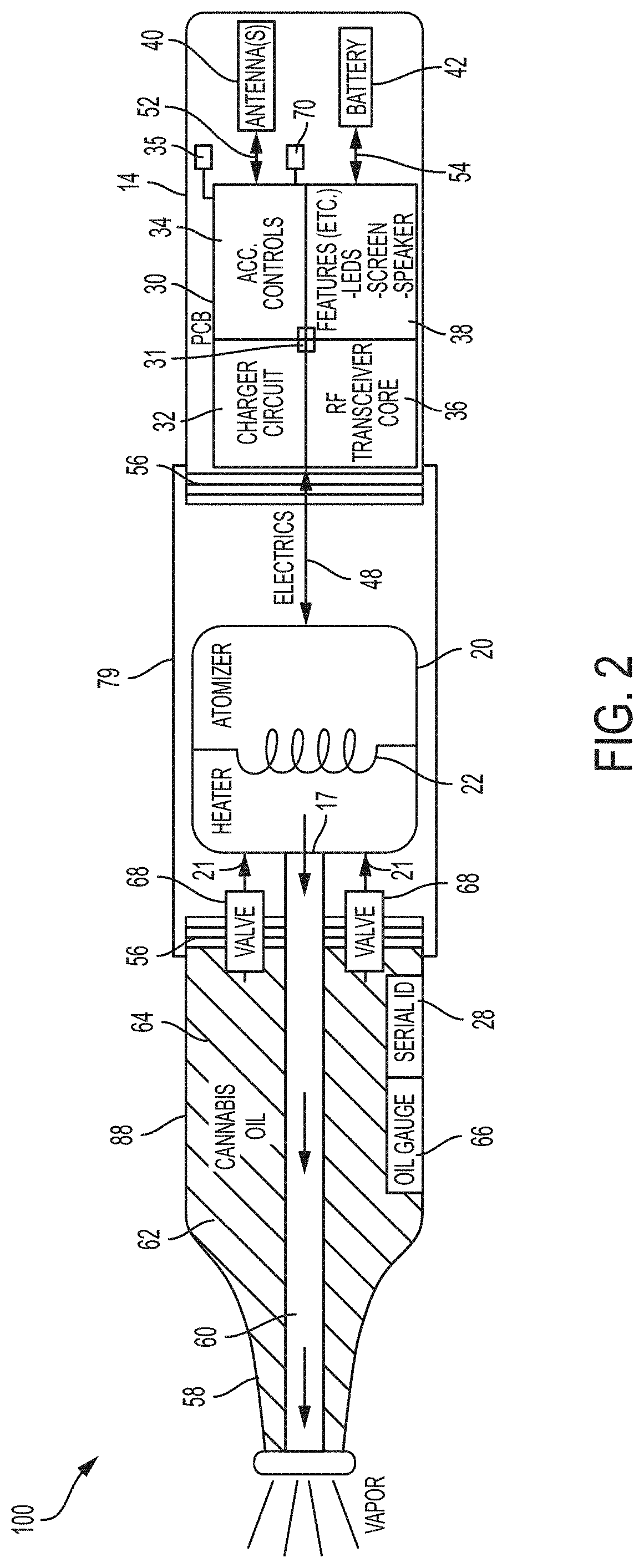
[0079]Referring to FIG. 2, another embodiment of vape device 100 is shown. In some embodiments, vape device 100 can comprise control assembly 14, atomizer assembly 79 and mouthpiece assembly 88 operatively coupled together in that order using mechanical connection means 56 to join the subassemblies together. Mechanical connection means 56 can comprise one or more of threaded connection means, magnetic connection means and friction or press-fit connection means, and any of the connection means 15 described above, including 510 threaded connectors. In some embodiments, mouthpiece assembly 88 can comprise a mouthpiece 58 in communication with the outlet of atomizer 20 via conduit 60. Mouthpiece assembly 88 can further comprise a payload reservoir 62 that can be filled with a payload 64 that may be liquid or oil. The payload 64 can flow from payload reservoir 62 to inlet 21 of atomizer 20 via one or more valves 68. In some embodiments, mouthpiece assembly 88 can comprise I...


PUM


Abstract

A vape device system including a payload reservoir that is identified by a payload identifier and that is configured to hold a substance for atomization. A processor is configured to determine an operational setting based on at least one of the payload identifier and a secondary data, which may include user information, prescription information, location information, payload information, historical vape device usage information, and historical payload reservoir information. A vape device system, and method of using the same, that includes a vape device and a computing device that includes the processor. A method of controlling a vape device including determining an operational setting of the vape device based on the payload identifier and / or secondary data. The operational settings may include a duty cycle setting, a temperature setting, an operational time duration, a dosage setting, and a security setting.

Description

CROSS-REFERENCE TO RELATED APPLICATIONS[0001]This application is a continuation-in-part of and claims priority to U.S. patent application Ser. No. 15 / 921,144, filed on Mar. 14, 2018, which is based on and claims priority to U.S. Provisional Application Ser. No. 62 / 471,751, filed on Mar. 15, 2017, each of which is incorporated herein by reference in its entirety.[0002]This application is also a continuation-in-part of and claims priority to International Patent Application No. PCT / CA2019 / 050316, filed on Mar. 14, 2019, which (i) is a continuation-in-part of and claims priority to U.S. patent application Ser. No. 15 / 921,144, filed on Mar. 14, 2018, and (ii) is based on and claims priority to U.S. Provisional Application Ser. No. 62 / 733,286 filed on Sep. 19, 2018, each of which is incorporated herein by reference in its entirety.STATEMENT REGARDING FEDERALLY SPONSORED RESEARCH OR DEVELOPMENT[0003]Not applicable.STATEMENT REGARDING JOINT RESEARCH AGREEMENT[0004]Not applicable.BACKGROUND...

Claims


Application Information

Patent Timeline
Patent Type & Authority Patents(United States)
IPC IPC(8): A24F47/00G06F21/32G06F21/31A61M15/06A24F40/53A24F40/65A24F40/10A24F40/49
CPCG06F21/32A24F40/53A24F40/65A61M15/06G06F21/31A24F40/10A24F40/49A61M2205/123A61M2205/6009
Inventor POPPLEWELL, PETERSTEWART, ANDREWPENNEY, STEVEN
Owner CANOPY GROWTH CORP
Learn More