Device of bi-spiral cleaning brush

a cleaning brush and bi-spiral technology, applied in the field of cleaning brushes, can solve the problems of easily affecting the cleaning efficiency of the cleaning unit, so as to achieve good cleaning efficiency, enhance the effect of water distribution and large contact surfa

Active Publication Date: 2021-09-07
TUNG AN DEV
View PDF3 Cites 0 Cited by
  • Summary
  • Abstract
  • Description
  • Claims
  • Application Information

AI Technical Summary

Benefits of technology

[0008]The main purpose of the present invention is to provide a cleaning unit comprising a plurality of cleaning beans fixed on a surface of a carrier in a bi-spiral arrangement, where the cleaning beans are arranged in an unequally-spaced manner at center of the carrier along a baseline for obtaining positive and negative directions on rotating; the bi-spiral cleaning unit generates a number of flow fields while, in addition to a perpendicular direction, a transverse direction toward an object to be cleaned is obtained; the flow fields are introduced by pushing a solution from the center to the different directions outwardly; and, thus, dirt can be discharged more easily than traditional matrix cleaning devices with water distribution enhanced as compared to unidirectional spiral cleaning devices while a large contact surface, a good cleaning efficiency, and a high decontamination ratio are achieved.

Problems solved by technology

But, because the third prior art uses its protrusions in a matrix arrangement with their tops formed into surfaces having high smoothness as flat planes and the second prior art also has its protrusions formed into flat planes in a matrix arrangement, the above two prior arts do not effectively contact the precision electronic components whose surfaces are irregular.
Thus, the above four prior arts may easily make particles spraying non-directionally during cleaning.
Not only the particles are not removed directionally, but also they might be trapped between the cleaning units and the precision electronic components, not to mention the damages thus caused to the precision electronic components.
Hence, the prior arts do not fulfill all users' requests on actual use.

Method used


Image

  • Device of bi-spiral cleaning brush
  • Device of bi-spiral cleaning brush

Examples


Embodiment Construction

[0013]The following description of the preferred embodiment is provided to understand the features and the structures of the present invention.

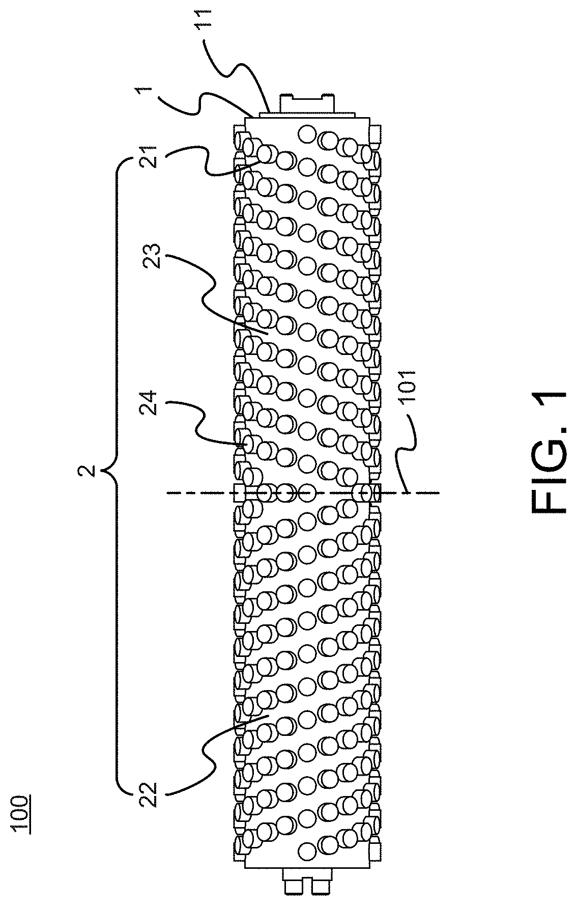
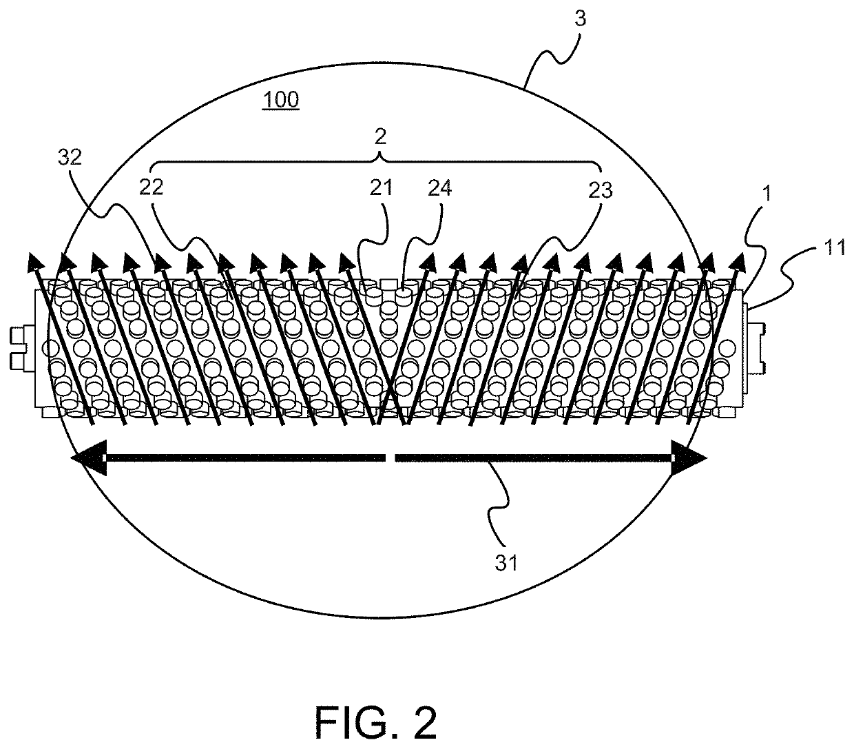
[0014]Please refer to FIG. 1 and FIG. 2, which are a view showing a preferred embodiment according to the present invention; and a view showing a state-of-use. As shown in the figures, the present invention is a device of bi-spiral cleaning brush 100, comprising a carrier 1 and a bi-spiral cleaning unit 2. Therein, according to a given request, the carrier 1 and the bi-spiral cleaning unit 2 use different polymer materials like a composite, sponge, polyurethane (PU), polyvinyl alcohol (PVA) and / or a polymer material as soft foams to be foamed and formed integrally.

[0015]The carrier 1 has a cylindrical shape, where a sleeve unit 11 is set in center to be assembled with an actuating device (not shown in the figure).

[0016]The bi-spiral cleaning unit 2 is disposed on an outer edge of the carrier 1 and comprises a plurality of cleaning beans 21 fi...


PUM


Abstract

A cleaning brush is provided. A cleaning unit comprises cleaning beans fixed on a surface of the carrier in a bi-spiral arrangement. The cleaning beans are arranged in an unequally-spaced manner on center of the carrier along a baseline; and, thus, bi-spirals are formed on the center and coiled in two different outward directions. Two annular spiral curve paths are formed with the cleaning beans as coiling the carrier and extending along the two directions. When the carrier cleans an electronic device, a solution or cleaning agent is discharged along the curve paths in spiral tangential directions. Hence, the bi-spiral cleaning unit obtains positive and negative directions on rotating to create a plurality of flow fields. Dirt is discharged easily with water distribution enhanced as compared to unidirectional spiral cleaning devices while a large contact surface, a good cleaning efficiency, and a high decontamination ratio are achieved.

Description

TECHNICAL FIELD OF THE INVENTION[0001]The present invention relates to a cleaning brush; more particularly, during a cleaning motion, to applying a bi-spiral way to push dirt with directivity from center toward two outward ends for providing more effective cleaning efficiency and effectively improving water distribution.DESCRIPTION OF THE RELATED ARTS[0002]A first prior art for cleaning precision electronic components (such as silicon wafer, hard drive disk, semiconductor and CPU chip) is a general device made of an elastic porous sponge of polyvinyl acetal. Multiple protrusions are set on a lateral surface. The tops of the protrusions rotate and contact the surface of a to-be-cleaned object for cleaning. Therein, the protrusions are arranged into a matrix; and the top of each protrusion is formed of a surface layer having high smoothness. Thus, with the coordination of an actuator, the multiple protrusions on the surface are used to clean precision electronic components.[0003]A sec...

Claims


Application Information

Patent Timeline
Patent Type & Authority Patents(United States)
IPC IPC(8): A46B9/02B08B1/00B08B1/04B08B3/04A46B9/00G03G21/00A46B13/00H01L21/67
CPCA46B9/025A46B9/005A46B9/026A46B13/001B08B1/002B08B1/04B08B3/04G03G21/0058H01L21/67046A46B2200/30
Inventor KU, CHIH-ANCHUANG, TZU-YENCHAO, HUNG-CHIEHZHANG, FU-QIANG
Owner TUNG AN DEV
Why Eureka
Try Eureka