Fuel cell membrane-electrode assembly
a fuel cell and membrane electrode technology, applied in the direction of fuel cells, cell components, electrical equipment, etc., can solve the problems of rapid progress of carbon corrosion and generation of corrosion, and achieve the effects of improving water distribution, preventing corrosion, and improving battery performan
- Summary
- Abstract
- Description
- Claims
- Application Information
AI Technical Summary
Benefits of technology
Problems solved by technology
Method used
Image
Examples
example 1
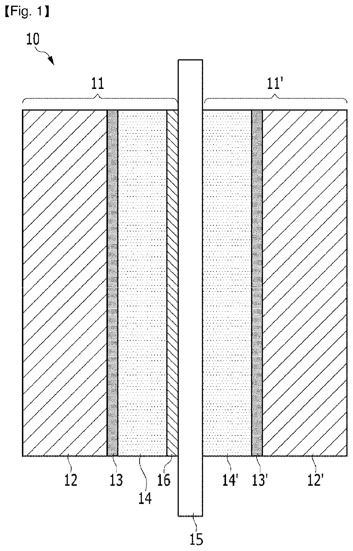
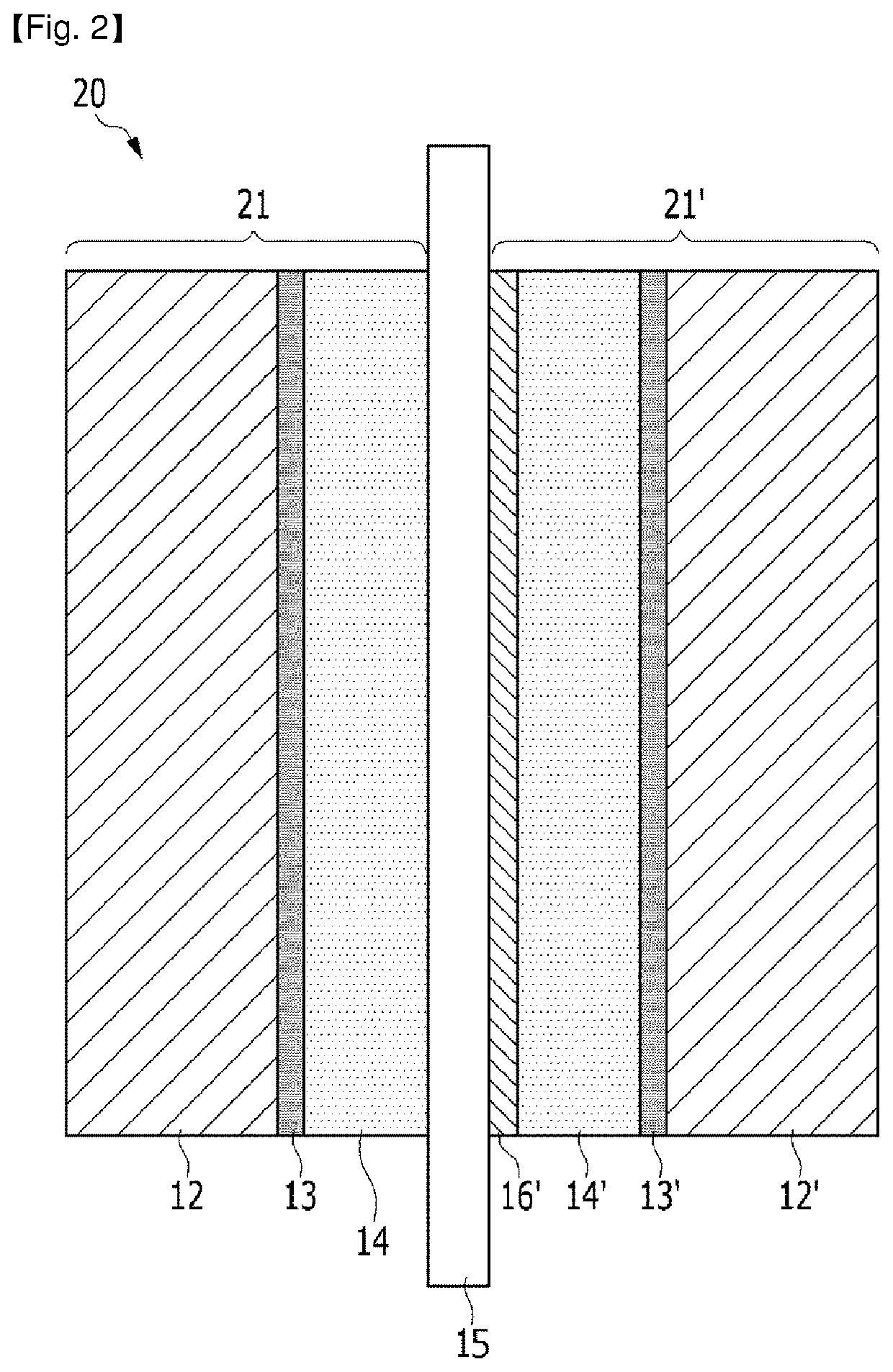
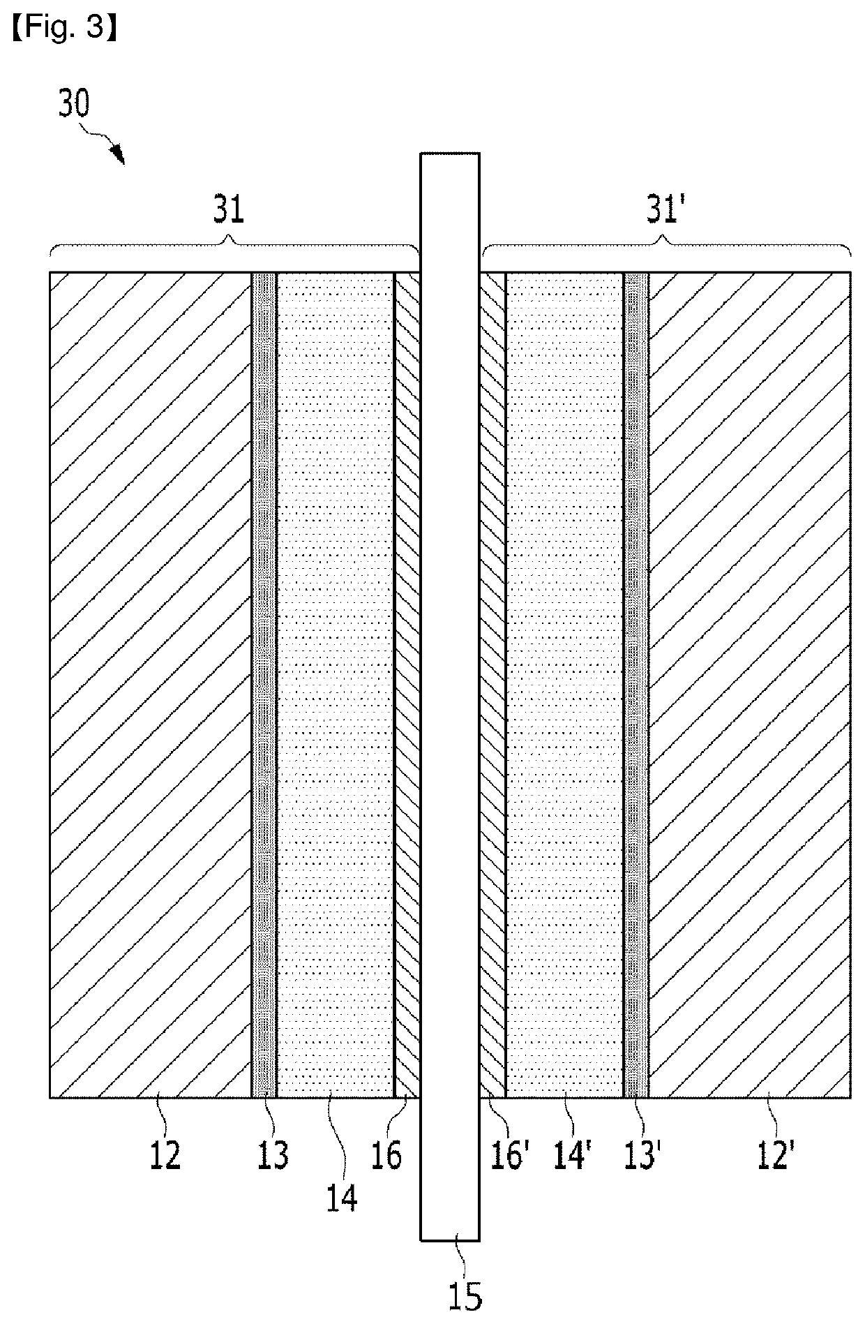
[0115](Manufacturing a First Catalyst Layer)
[0116]A first catalyst (Tanaka Kikinzoku Kogyo TEC36F52) having 52 wt % of a Pt3Co alloy supported on 48 wt % of carbon was prepared.
[0117]A first catalyst layer composition was prepared by mixing 65 wt % of the first catalyst with 35 wt % of Nafion (DuPont Company).
[0118]A first catalyst layer was manufactured by coating the first catalyst layer composition on a fluorinated ethylene propylene (FEP) film and sufficiently drying the first catalyst layer composition coated on the FEP film at a temperature of 90° C. in a convection oven for 5 hours, and the first catalyst layer was used as a cathode catalyst layer forming a cathode electrode and an anode catalyst layer forming an anode electrode.
[0119](Manufacturing a Second Catalyst Layer)
[0120]A second catalyst consisting of 94 wt % of Ir8Ru2FeOx (0.5≤x≤2) and 6 wt % of SiO2 was manufactured by adding 80 wt % of SiO2 to 20 wt % of a mixture obtained by mixing chloroiridic acid (H2IrCl8), ru...
example 2
[0125]A second catalyst having 42 wt % of IrRuOx (0.5≤x≤2) and 2 wt % of SiO2 supported on 56 wt % of the stabilization carbon was manufactured by adding 55.6 wt % of SiO2 to 20 wt % of a mixture obtained by mixing chloroiridic acid (H2IrCl8) with ruthenium trichloride (RuCl3) such that an atomic ratio of Ir and Ru became 1:1 to obtain a SiO2-added mixture, supporting the SiO2-added mixture on 24.4 wt % of a stabilization carbon formed by heat-treating Ketjen black at 2250° C., primarily heat-treating the SiO2-added mixture supported on the stabilization carbon at a temperature of 300° C. under a hydrogen atmosphere to obtain a primarily heat-treated material, secondly heat-treating the primarily heat-treated material at a temperature of 250° C. under an air atmosphere to obtain a secondly heat-treated material, and removing a portion of SiO2 from the secondly heat-treated material through NaOH. At this time, 5 parts by weight of IrRuOx (0.5≤x≤2) was included with respect to 100 par...
example 3
[0127]A second catalyst having 42 wt % of IrRu2Ox (0.5≤x≤2) and 2 wt % of SiO2 supported on 56 wt % of the stabilization carbon was manufactured by adding 55.6 wt % of SiO2 to 20 wt % of a mixture obtained by mixing chloroiridic acid (H2IrCl6) with ruthenium trichloride (RuCl3) such that an atomic ratio of Ir and Ru became 1:2 to obtain a SiO2-added mixture, supporting the SiO2-added mixture on 24.4 wt % of a stabilization carbon formed by heat-treating Ketjen black at 2250° C., primarily heat-treating the SiO2-added mixture supported on the stabilization carbon at a temperature of 300° C. under a hydrogen atmosphere to obtain a primarily heat-treated material, secondly heat-treating the primarily heat-treated material at a temperature of 250° C. under an air atmosphere to obtain a secondly heat-treated material, and removing a portion of SiO2 from the secondly heat-treated material through NaOH. At this time, 5 parts by weight of IrRu2Ox (0.5≤x≤2) was included with respect to 100 p...
PUM
| Property | Measurement | Unit |
|---|---|---|
| thickness | aaaaa | aaaaa |
| wt % | aaaaa | aaaaa |
| voltage | aaaaa | aaaaa |
Abstract
Description
Claims
Application Information
 - R&D
- Intellectual Property
- Life Sciences
- Materials
- Tech Scout
- Unparalleled Data Quality
- Higher Quality Content
- 60% Fewer Hallucinations
Browse by: Latest US Patents, China's latest patents, Technical Efficacy Thesaurus, Application Domain, Technology Topic, Popular Technical Reports.
© 2025 PatSnap. All rights reserved.Legal|Privacy policy|Modern Slavery Act Transparency Statement|Sitemap|About US| Contact US: help@patsnap.com


