Brake system for an articulated vehicle

a technology for brake systems and articulated vehicles, applied in brake systems, asr control systems, braking components, etc., can solve problems such as uncontrolled vehicle spinout, wheel lockup, slippage or skid on the road surface, etc., and achieve the effect of reducing the rotational speed of the traction devi

Active Publication Date: 2021-09-14
CATERPILLAR INC
View PDF15 Cites 0 Cited by
  • Summary
  • Abstract
  • Description
  • Claims
  • Application Information

AI Technical Summary

Problems solved by technology

Under these conditions, or in panic stop situations, a driver will often apply excessive brake pressure, thereby causing the wheels to lockup and slip or skid on the road surface.
Wheel lockup conditions can lead to loss of directional stability and, possibly, uncontrolled vehicle spinout.

Method used


Image

  • Brake system for an articulated vehicle
  • Brake system for an articulated vehicle
  • Brake system for an articulated vehicle

Examples


Embodiment Construction

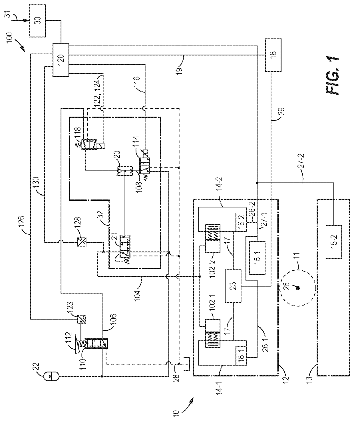
[0016]Turning first to FIG. 1, FIG. 1 depicts a first brake system 100 for use in braking an articulated vehicle 10. The articulated vehicle 10 includes a front cab 12 and a rear body 13 separated by an articulation joint 11 (depicted as a dashed outline in FIGS. 1 and 2). The front cab 12 may include an operator compartment and support the engine. The rear body 13 may support a dump body, a trailer, or other similar structures. The front cab 12 and rear body 13 may rotate relative to each other at the articulation joint 11, that rotates about the vertical axis 25.

[0017]The articulated vehicle 10 may include traction devices 14 that serve as ground engaging members for the articulated vehicle 10. For example, the traction devices 14 may include a left-side traction device 14-1 and a right-side traction device 14-2. The traction devices 14 may be disposed on opposite sides of an axle 17 that extends between the left-side traction device 14-1 and the right-side traction device 14-2. T...


PUM


Abstract

A brake system for an articulated vehicle is disclosed. The brake system includes a brake assembly coupled to a traction device, the brake assembly being configured to apply a brake-assembly pressure based on one of a hydro-mechanical pressure signal and an electro-mechanical pressure signal. A blocking valve is configured to block the hydro-mechanical pressure signal when closed. A brake controller, is configured to transmit an isolation signal configured to close the blocking valve and transmit an ABS control signal that is based on a commanded ABS brake pressure.

Description

TECHNICAL FIELD[0001]This disclosure relates to brake systems and, more specifically, to brake systems for an articulated vehicle.BACKGROUND[0002]Braking a vehicle in a controlled manner under adverse conditions such as rain, snow, or ice generally requires precise application of the brakes by the vehicle driver. Under these conditions, or in panic stop situations, a driver will often apply excessive brake pressure, thereby causing the wheels to lockup and slip or skid on the road surface. Wheel lockup conditions can lead to loss of directional stability and, possibly, uncontrolled vehicle spinout.[0003]In a continuing effort to improve the operational safety of vehicles, antilock braking systems have been developed. While such systems are adapted to control the braking of each braked wheel of a vehicle, some systems have been developed for controlling the braking of only a portion of the braked wheels. Generally, antilock brake systems are electrohydraulic and include a controller ...

Claims


Application Information

Patent Timeline
Patent Type & Authority Patents(United States)
IPC IPC(8): B60W30/18B60T8/171B60T8/172B60T8/176B60T15/02B60T13/68B60T8/32B60T8/34B60W10/10B60W10/188B60W30/045B60W10/20B60W10/12B60T7/12
CPCB60W30/18145B60T7/12B60T8/171B60T8/172B60T8/176B60T8/326B60T8/34B60T13/686B60T15/028B60W10/10B60W10/12B60W10/188B60W10/20B60W30/045B60T2201/16B60T2240/00B60T2250/00B60T2270/10B60T2270/20B60W2510/20B60W2520/28B60W2710/10B60W2710/12B60W2710/18B60W2710/20B60T7/042B60T13/662B60T8/3255B60T8/1708
Inventor WALENTA, CLAYTON D.WELTZER, ANTHONY J.
Owner CATERPILLAR INC
Why Eureka
Try Eureka