
Method for supplying air at a controlled temperature to a cabin of a land vehicle, and land vehicle

a technology for land vehicles and cabins, applied in vehicle heating/cooling devices, climate sustainability, air-treatment devices, etc., can solve the problems of insufficient surface operation, pump cycle operation, and rare heating, etc., to achieve easy adjustment, low energy consumption, and easy installation and maintenance.

Active Publication Date: 2021-10-05
LIEBHERR AEROSPACE TOULOUSE
View PDF6 Cites 1 Cited by
  • Summary
  • Abstract
  • Description
  • Claims
  • Application Information

AI Technical Summary

Benefits of technology

The invention proposes a method for supplying air at a controlled temperature to a vehicle's cabin using an air cycle system that is compact, reliable, and efficient. The method can lower energy consumption and heat the cabin with a high performance co-efficient. The system allows for easy adjustment of hot or cold thermal power production based on usage requirements and provides partial redundancy in case of failure. The use of a motorized turbocompressor simplifies the architecture and components, reduces airflow and pipeline dimensions, and results in a smaller and more cost-effective system. Overall, the method and system offer an efficient and adaptable solution for air conditioning in surface vehicles.

Problems solved by technology

It is rarely possible to envisage heating by inversion of the heat pump cycle, taking into account the fact that the ranges of environmental conditions in which the heat pump cycle can operate are relatively limited and insufficient to operate on-board a surface vehicle likely to encounter varied environmental conditions.
These two-phase cycle systems have the disadvantage of requiring heat transfer fluids which are halogeno-carbonaceous (chlorofluorocarbons (CFC), hydrochlorofluorocarbons (HCFC), hydrofluorocarbons (HFC)) or hydrofluoroolefins (HFO) which should no longer be used owing to their harmfulness to the environment and / or their danger to humans (destruction of the ozone layer, high potential for global warming, need to be collected by authorised bodies, toxicity, risk of ignition .
Furthermore, it has proved to be the case that two-phase cycles are poorly adapted to elevated external temperatures and can be interrupted under environmental conditions in which the air conditioning requirements are actually needed the most.
This results in considerable discomfort for the passengers, and even risks in terms of safety or preservation of goods.
However, it has proved to be the case that this first type of solution is not reliable or robust enough in use.
In fact, the electric compressors necessary for the first compression stage are fragile components which quickly undergo wear owing to the numerous stops and starts to which they are subjected in use.
Furthermore, this solution requires a plurality of rotating machines (first electric compressor stage, turbocompressor, four groups of electric fans) which are bulky, heavy, costly to install and to maintain and require relatively complex control logic.
However, it has the disadvantage of being relatively bulky, especially in terms of height.
This bulkiness in terms of height can prove to be particularly problematic in particular for rail vehicles in which air conditioning assemblies are generally placed in the roof and for which the total height is limited on the one hand to allow passage beneath bridges or through tunnels and on the other hand to promote the aerodynamics of the vehicle.
DE 102004063840 also describes an air conditioning method and device which can be switched between a cooling mode and a heating mode but the energy performances of which are not optimised.

Method used


Image

  • Method for supplying air at a controlled temperature to a cabin of a land vehicle, and land vehicle
  • Method for supplying air at a controlled temperature to a cabin of a land vehicle, and land vehicle
  • Method for supplying air at a controlled temperature to a cabin of a land vehicle, and land vehicle

Examples


first embodiment

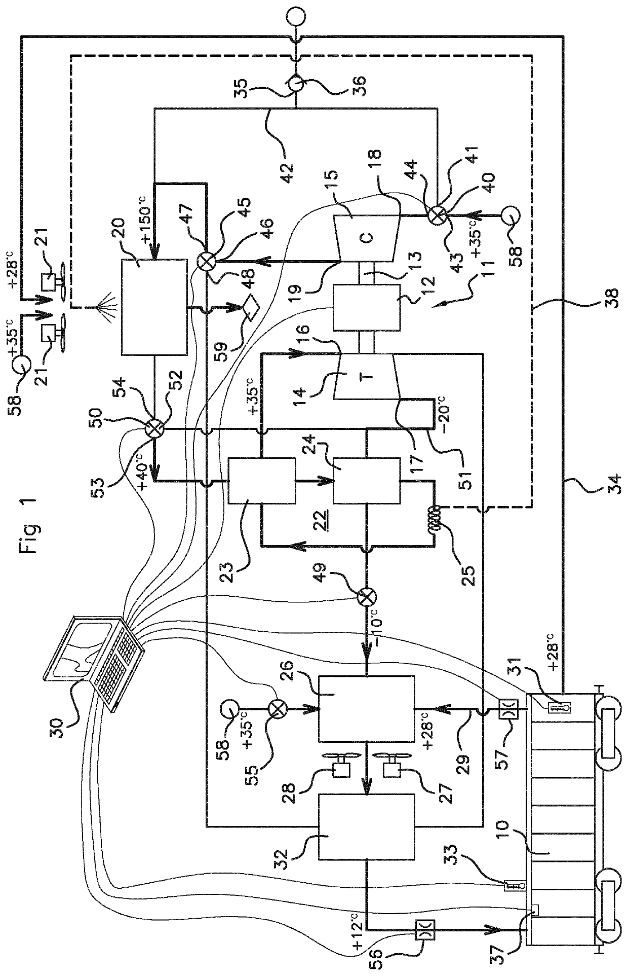
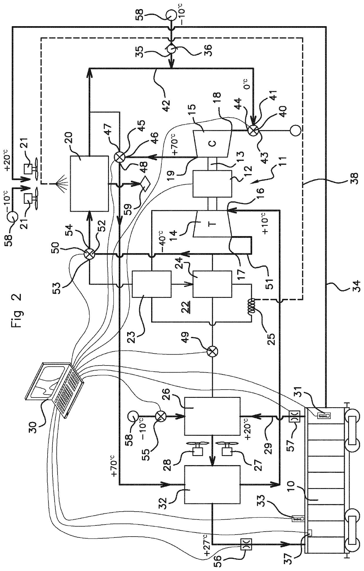
[0124]In the first embodiment illustrated in FIGS. 1 and 2, the air inlet 18 of the compressor 15 comprises a controlled three-way valve 40, of which one inlet 41 is connected by a conduit 42 to the first circuit of the intermediate exchanger 20, one inlet 43 is supplied with external fresh air 38, and having an outlet 44 connected to the air inlet 18 of the compressor 15.

[0125]The air outlet 19 of the compressor 15 is connected to an inlet 46 of a controlled three-way valve 45, of which one outlet 47 is connected to the conduit 42 leading to the first circuit of the intermediate exchanger 20 (conduit 42 connecting the air inlet 18 of the compressor 15 to the first circuit of the intermediate exchanger 20), and one outlet 48 is connected to the first circuit of the cabin heat exchanger 32.

[0126]A controlled valve 49 is interposed between the air outlet 17 of the turbine 14 and the mixing chamber 26, for example between the outlet of the second circuit of the condensing heat exchange...

second embodiment

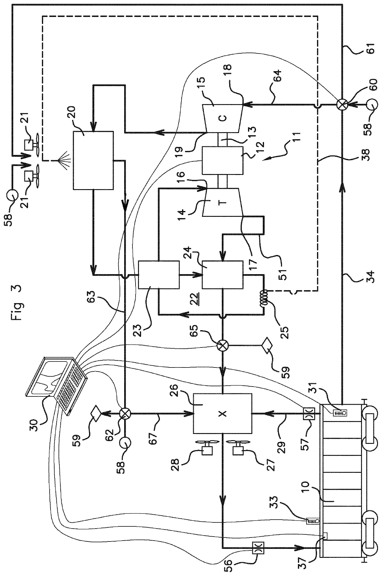
[0163]Thus, in this second embodiment, in the heating mode, the main air circuit flowing in the turbocompressor 11 and an airflow ejected to the outside, which can correspond to the airflow to be extracted from the cabin 10 for renewal of dioxygen in the cabin 10, and which serves to heat the airflow supplying the mixing chamber 26 and thus the cabin owing to the intermediate exchanger 20 which acts as a heat exchanger.

[0164]It should be noted that in a variant, not shown, of this second embodiment, the air inlet 18 of the compressor 15 can be supplied directly by drawing air specifically from the cabin 10 e.g. for ejecting foul air to the outside, along a different conduit from the recirculation and heating air passing into the second circuit of the intermediate exchanger 20.

[0165]Table 3 below shows, by way of non-limiting example, different typical values for flow rate, pressure and temperature at the air inlets and outlets of the turbine 14 of the compressor 15 of the turbocompr...


PUM


Abstract

The invention relates to a method for supplying air at a controlled temperature to a cabin of a surface vehicle in which at least one air cycle device is used, comprising at least one motorized turbocompressor. The air inlet of the turbine is arranged to receive a compressed airflow from the compressor. At least one exchanger is interposed between the air outlet of the compressor and the air inlet of the turbine. The air inlet of the compressor is arranged to receive air at a pressure greater than or equal to atmospheric pressure. The invention likewise relates to a surface vehicle comprising at least one such air cycle device.

Description

RELATED APPLICATION[0001]This application is a National Phase of PCT / EP2017 / 084746, filed on Dec. 28, 2017, which claims the benefit of priority from French Patent Application No. 16 63532, filed on Dec. 29, 2016, the entirety of which are incorporated by reference.BACKGROUNDField of the Invention[0002]The invention relates to a method for supplying air at a controlled temperature to a cabin of a surface vehicle—in particular a rail vehicle—in which at least one air cycle device is used. It relates to a surface vehicle—in particular a rail vehicle—comprising at least one air cycle device.Description of Related Art[0003]Throughout the text the following terminology will be adopted:[0004]“surface vehicle” means any transport vehicle moving on the surface of the Earth in the atmosphere and includes in particular wheel-borne (rail vehicles running on rails and road vehicles) and ships (vehicles moving on water); and excluding in particular flying craft such as aircraft, spacecraft and s...

Claims


Application Information

Patent Timeline
IPC IPC(8): B61D27/00B60H1/03B60H1/32
CPCB61D27/0018B60H1/039B60H1/3213B60H1/3232B60H2001/3255B60H2001/3297Y02T30/00
Inventor FRANKENBERGER, ANNEKATHRINKRAWANJA, ANDREASMENGELLE, THIERRY
Owner LIEBHERR AEROSPACE TOULOUSE
Learn More