Check patentability & draft patents in minutes with Patsnap Eureka AI!

Method for driving a valve for regulating the flow rate of fuel gas towards a burner, in particular for condensation boilers having high power modulation

a modulation valve and fuel gas technology, which is applied in the direction of instruments, lighting and heating apparatus, magnetic bodies, etc., can solve the problems of unsuitable devices for achieving precise gas metering, too low depression signal to be detected by the gas-modulation valve, and limit of a solution of this type. , to achieve the effect of widening the modulation rang

Active Publication Date: 2021-10-05
SIT SPA
View PDF10 Cites 0 Cited by
  • Summary
  • Abstract
  • Description
  • Claims
  • Application Information

AI Technical Summary

Benefits of technology

This method enables a wider range of modulation in minimum gas flow rates, improving the ability to adapt to different gases and ensuring efficient and stable combustion, while maintaining cost-effectiveness by not requiring substantial modifications to the valve or control hardware.

Problems solved by technology

The limitations of a solution of this type are known.
In particular, for air flow rates below a particular value, the depression signal is too low to be detected by the gas-modulation valve.
For air flow rates close to the minimum flow rate value, the gas-modulation valve exhibits imprecise behaviour, in which the correspondence of the depression to the gas flow rate is no longer valid; thus, under these conditions, the device is unsuitable for achieving precise gas metering.
Again, a limitation of this second type of solution lies in the size of the range of power modulation (Pmin:Pmax) which can be achieved.
Using a pneumatically controlled boiler, this range is typically 1:5-1:7, possibly reaching 1:10 with the use of special, expensive Venturi mixer devices, but without having the advantages of a closed-loop system.
This poses two main problems, one relating to the ability of the sensor means to detect the quality of combustion through the range of modulation, and the other relating to the ability to deliver air and gas within this wide range of modulation.
It follows that, in the prior art, the valves have a gas flow rate modulation capacity which is insufficient both for achieving the required wide range of modulation and for being able to adapt automatically to a different type of gas.

Method used


Image

  • Method for driving a valve for regulating the flow rate of fuel gas towards a burner, in particular for condensation boilers having high power modulation
  • Method for driving a valve for regulating the flow rate of fuel gas towards a burner, in particular for condensation boilers having high power modulation
  • Method for driving a valve for regulating the flow rate of fuel gas towards a burner, in particular for condensation boilers having high power modulation

Examples


Embodiment Construction

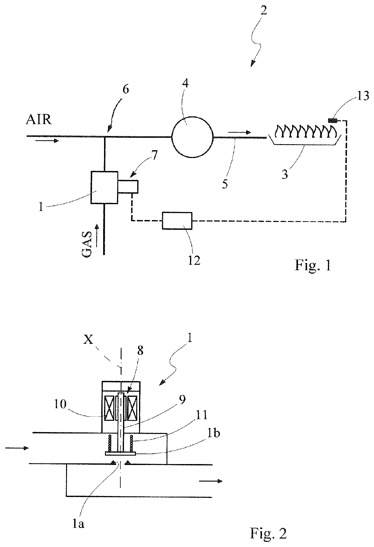
[0022]Referring first to FIG. 1, a valve for controlling the delivery of a fuel gas, operating in accordance with the method of the present invention, is denoted as 1 and shown merely schematically. The valve is associated with a boiler plant, preferably a condensation boiler plant, labelled as a whole as 2, including a premix burner apparatus 3 which has a modulable thermal power and the flame of which is intended to heat an intermediate fluid circulating in the boiler plant.

[0023]The burner apparatus 3 is of the forced-ventilation type, and for this purpose the use of a fan 4 is provided, positioned in the suction or inlet of the air / gas fuel mixture heading to the burner. In the example of FIG. 1, a conduit 5, in which a mixing zone 6 is defined between the airflow supplied by the fan 4 and the gas flow delivered by the valve 1, extends between the fan 4 and the burner.

[0024]The thermal power achievable at the burner can be regulated (depending on the rate of rotation of the fan)...


PUM

PropertyMeasurementUnit
carrier frequencyaaaaaaaaaa
frequencyaaaaaaaaaa
carrier frequencyaaaaaaaaaa

Abstract

A method for modulating a valve regulating the flow rate of gas towards a burner is presented. The valve with the associated closure member configured to operate with a predetermined characteristic curve, the flow rate delivered being proportionally related to the strength of a first current signal sent to the modulator such that the flow rate can be modulated, using the proportionality, within a range of modulation between a maximum flow rate and a minimum flow rate. To deliver controlled gas flow rates that are below the minimum flow rate, the modulator is driven with a second PWM voltage signal capable of generating a particular second PWM current signal, to move the closure member of the valve according to the second signal. First and second time intervals correspond to successive durations of high signal and low signal, respectively, the sum being equal to a period of the second signal.

Description

TECHNICAL FIELD[0001]The present invention relates to a method for driving a modulating valve for regulating the flow rate of fuel gas towards a burner, in particular for condensation boilers having high power modulation, having the features set out in the preamble of main claim 1.TECHNOLOGICAL BACKGROUND[0002]In the technical field of gas-operated condensation boilers, there is the need to vary the flow rate of gas in a manner coordinated with the flow rate of air so as to keep the air / fuel ratio within a narrow interval corresponding to combustion which is optimised both for gas emissions and for consumption.[0003]In conventional condensation boilers, this is achieved by way of a device through which the air is passed and which, by way of a variable-section configuration in the airflow direction in a convergent / divergent profile, creates a depression, of a magnitude which is dependent on the strength of the airflow, in one of said sections by the Venturi effect. Said depression se...

Claims


Application Information

Patent Timeline
Patent Type & Authority Patents(United States)
IPC IPC(8): F23N1/00F16K31/06F23L5/02G05D7/06H01F7/06H01F7/18F24H8/00
CPCF23N1/005F16K31/0675F23L5/02F23N1/002G05D7/0635H01F7/064H01F7/18F23N2235/14F23N2235/16F23N2237/10F24H8/00H01F2007/1888
Inventor ABATE, MAURIZIO ACHILLEMARCANTONIO, MAURIZIOPIROVANO, GIANCARLO
Owner SIT SPA
Features
  • R&D
  • Intellectual Property
  • Life Sciences
  • Materials
  • Tech Scout
  • Unparalleled Data Quality
  • Higher Quality Content
  • 60% Fewer Hallucinations
Learn More