System and method of hot gas defrost control for multistage cascade refrigeration system

a refrigeration system and cascade technology, applied in refrigeration components, mechanical equipment, lighting and heating apparatus, etc., can solve the problems of difficulty in controlling temperature and refrigerant flow during the defrost process, inability to provide tubes for heater rods, and inability to meet the requirements of use, so as to reduce the variability, increase the ease of design and implementation, and reduce the effect of ice accumulation

Active Publication Date: 2021-10-05
TRANE TECH LIFE SCI LLC
View PDF10 Cites 0 Cited by
  • Summary
  • Abstract
  • Description
  • Claims
  • Application Information

AI Technical Summary

Benefits of technology

[0008]The present invention fulfills this need by removing the variability of blended liquid refrigerant and hot gas mixtures by utilizing more advanced liquid refrigerant expansion devices, which include, without limitation, PWM and stepper valves which can be fully closed to prevent the flow of refrigerant. Thus, the present invention provides an improved system and method for hot gas defrost control for multistage, cascade refrigeration systems which, in contrast to existing methods and designs of hot gas defrost systems in multistage refrigeration systems, can defrost an evaporator coil with greater flexibility and increased ease of design and implementation while maintaining air in the evaporator coil below the freezing point of water.
[0013]The present invention allows for more robust hot gas defrost function for multistage refrigeration systems, such that it is unaffected by temperature changes of the condensing fluid (ambient air temperature for air cooled condensers, water temperature for water cooled condensers), and can be readily adapted to any refrigerant suitable for a selected temperature range. This is done by using the principles of saturated temperature and pressure, and by using the properties of one refrigerant to impose conditions on another through a heat exchanger between the fluids.

Problems solved by technology

Interfacing with the unit by opening the insulated cabinet space will introduce moisture via the air that will eventually cause frost and ice to build up on the evaporator coil.
Although robust, should a design require more evaporator coil capacity, the tubes being used for the heater rods may not be available.
A problem with usual hot gas defrost methodologies is the difficulty involved with the control of temperatures and refrigerant flow during the defrost process.
This blend of expanded liquid refrigerant and the short-cycled hot gas is hard to achieve, can require several iterations, and is restricted to one set of environmental conditions to work.
If these variables are not accounted for, the temperature of the heat exchanger can become too cold or too hot; in one instance making for a poorly performing second stage defrost cycle, and in another instance a defrost cycle that damages the second stage compressor due to high temperatures and pressures.
While existing methodologies may be suitable for laboratory or other thermally stable environments, they are not suitable for industrial applications where temperatures may vary from near 0° C. to 35° C. or higher.

Method used


Image

  • System and method of hot gas defrost control for multistage cascade refrigeration system

Examples


example

[0022]The present invention is more particularly described in the following non-limiting example, which is intended to be illustrative only, as numerous modifications and variations therein will be apparent to those skilled in the art.

Example—Hot Gas Defrost Cycle Operation

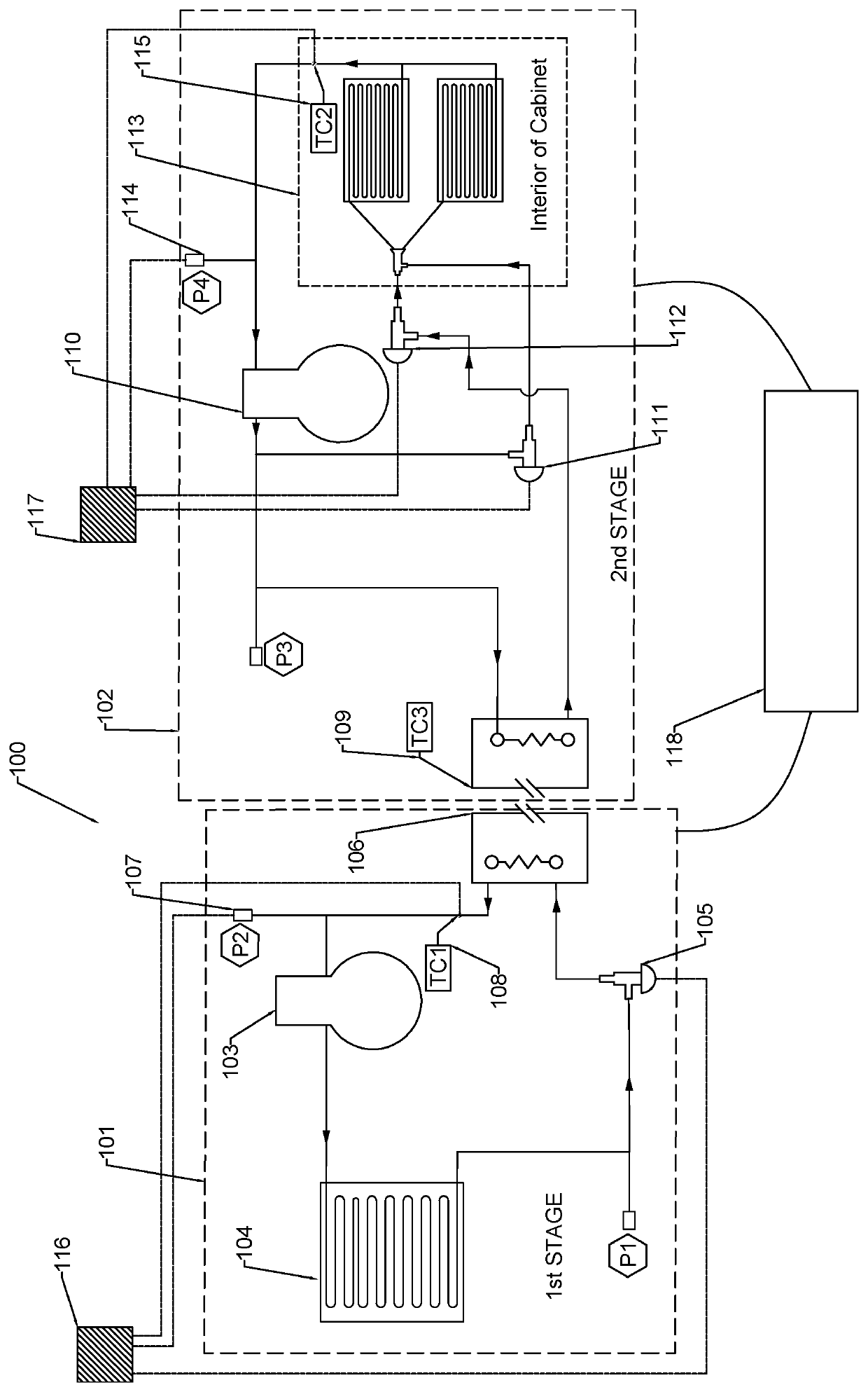
[0023]In this example, refrigerant R-404a is used in the first stage, and refrigerant R-508B is used in the second stage, given a design criterion where a refrigeration system must operate at −80° C. in the evaporator enclosure. As during normal operating conditions, the compressor operating conditions during defrost are critical to performance and longevity. As such, operational limits exist to which we must adhere. The upper limit of compressor operation can vary but is generally set by compressor manufacturers and industry experts to be 300PSIA of discharge pressure and a compression ratio of around 10:1 between suction pressure and discharge pressure. If operating at 300PSIA, any liquid R-508B that exists in t...


PUM


Abstract

The present invention provides a system and method for an improved multistage, cascade refrigeration system using hot gas defrost to rid the evaporator of ice build-up which accumulates over time, while the air in the evaporator enclosure remains below the freezing point of water. The present invention thus provides greater defrost flexibility with increased ease of design and implementation than current refrigeration systems, which allows for more robust hot gas defrost function for multistage refrigeration systems, such that it is unaffected by temperature changes of the condensing fluid (ambient air temperature for air cooled condensers, water temperature for water cooled condensers), and can be readily adapted to any refrigerant suitable for a selected temperature range.

Description

CROSS REFERENCE TO RELATED APPLICATIONS[0001]The present application claims priority to U.S. Provisional Application No. 62 / 857,047, filed Jun. 4, 2019, which is incorporated herein by reference in its entirety.FIELD OF THE INVENTION[0002]The present invention relates to refrigeration systems and, in particular, to an improved multistage, cascade refrigeration system which provides greater defrost flexibility with increased ease of design and implementation compared to current refrigeration systems.BACKGROUND[0003]Multistage, cascade refrigeration systems generally consist of two complete refrigeration circuits that are linked through a heat exchanger. The higher temperature system, or first stage, will have an air-cooled or water-cooled condenser, a compressor and an evaporator that is part of the central heat exchanger. The lower temperature system, or second stage, will have an evaporator in an accessible insulated cabinet space, a compressor, and a condenser that is part of the ...

Claims


Application Information

Patent Timeline
Patent Type & Authority Patents(United States)
IPC IPC(8): F25B47/02F25B41/22F25B41/31F25B7/00F25B40/06F25B41/345F25B41/385
CPCF25B47/022F25B7/00F25B40/06F25B41/22F25B41/31F25B41/347F25B41/385F25B2341/064F25B2347/02F25B2400/0403F25B2400/061F25B2700/191F25B2700/2101F25B2700/195F25B2700/1931F25B2700/1933F25B2700/2116F25B49/02Y02B30/70F25B41/34F25B2400/0411
Inventor FARRAR, DAVID SCOTTVUKSIC, JAMES S.LYDICK, TRACESCHOEPPNER, THOMASROBERTS, ALEX
Owner TRANE TECH LIFE SCI LLC
Why Eureka
Try Eureka