Distance measuring element

a technology of distance measurement and element, applied in the field of distance measuring element, can solve the problems of color value, difficult inability to identify a point, etc., and achieve the effect of improving the distance measuring elemen

Active Publication Date: 2021-10-19
ROBERT BOSCH GMBH
View PDF7 Cites 0 Cited by
  • Summary
  • Abstract
  • Description
  • Claims
  • Application Information

AI Technical Summary

Benefits of technology

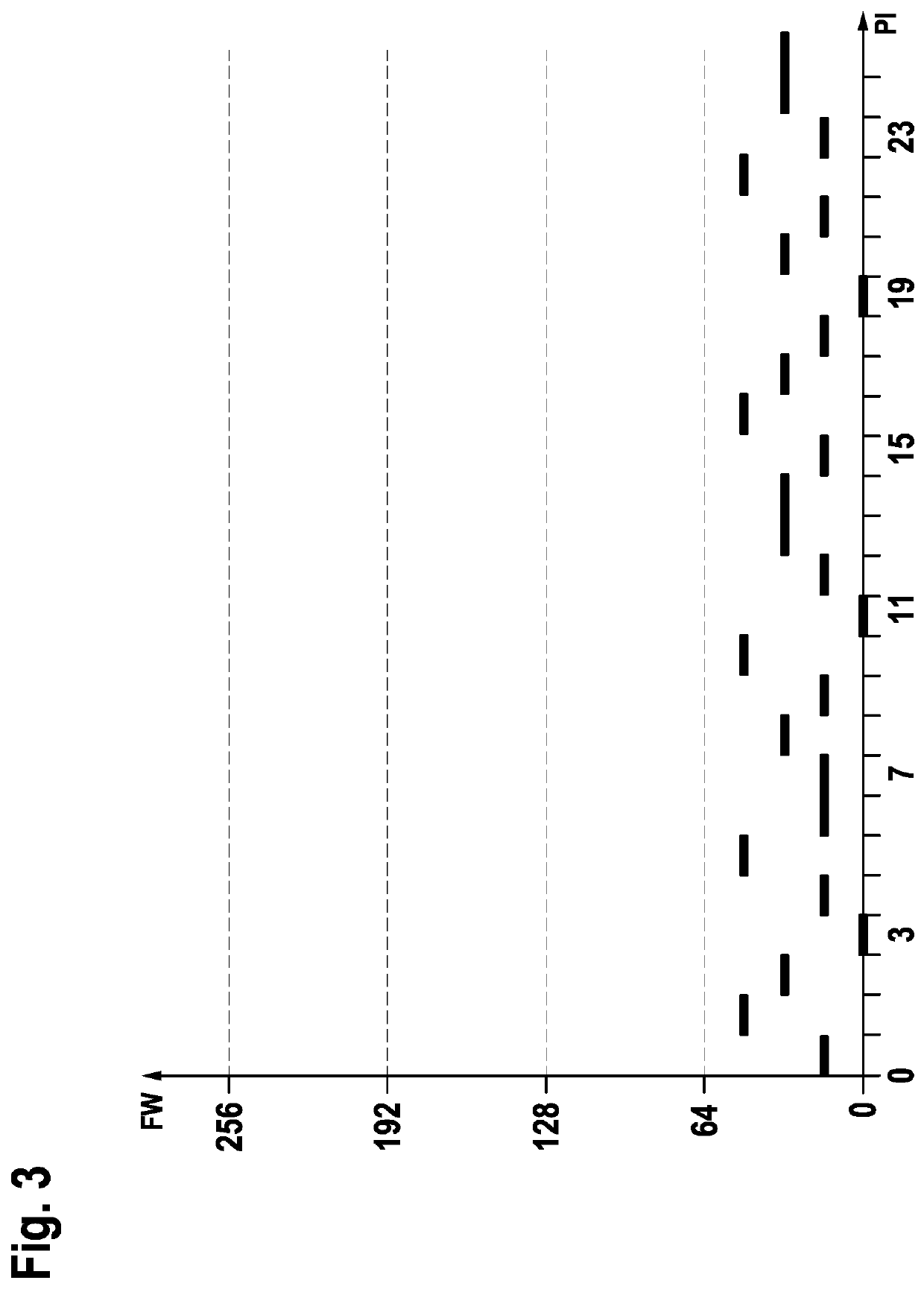
[0014]For the distance measuring element, a classification methodology for the surface pattern is thereby devised that renders possible an improved distance measurement from close proximity and from a distance by non-repetitively forming subpatterns on different scales of the surface pattern.
[0025]An advantageous further embodiment of the distance measuring element in accordance with the present invention has the feature that a color value or an intensity value may be superimposed by summing. A multiplicity of different embodiments of the surface pattern of the distance measuring element is thereby facilitated.
[0026]Another advantageous embodiment of the distance measuring element in accordance with the present invention has the feature that the distance element is at least one of the following: printable, paintable, adhesive, illuminable. A high degree of technological diversification of the distance measuring element is advantageously facilitated in this manner as well.
[0027]Another advantageous embodiment of the device in accordance with the present invention provides that the surface pattern be dithered. This advantageously simplifies a manufacturing process for the distance measuring element because a large value range may in a sense be simulated or replicated by a few values.
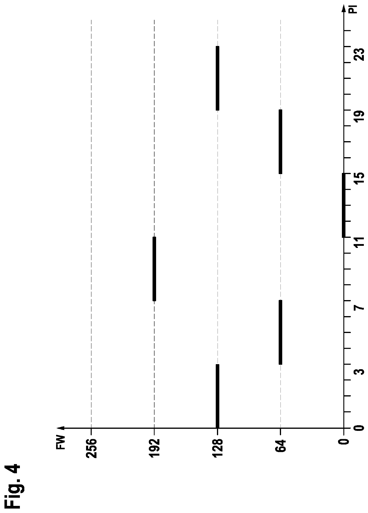
[0028]Another advantageous embodiment of the device in accordance with the present invention has the feature that the value ranges are represented by powers of two. At least two values are needed to be able to distinguish among image elements. Accordingly, the total number of distinguishable values is 2N, N being the number of value ranges (scales). Reducing the values to be distinguished lessens the accuracy requirement related to a color to be applied and the intensity thereof. By specifying powers of two, an optimum use of a value range, respectively of a scale is made possible, whereby a maximum contrast of the pattern of the distance measuring element is attainable. The result is thereby that a stereo camera enhances the ready recognizability of the pattern of the distance measuring element for purposes of distance measurement. Moreover, technical requirements related to a sensor of the stereo camera may thereby be advantageously reduced.

Problems solved by technology

Such an identification is difficult to impossible in the case of object surfaces having a homogeneous color gradient, in particular.
For that reason, it is not possible to identify a point by the color value thereof or by that of the neighboring points thereof in such a case.

Method used


Image

  • Distance measuring element
  • Distance measuring element
  • Distance measuring element

Examples


Embodiment Construction

[0040]A main feature of the present invention is, in particular, to provide a method and a device which may be used to design surface patterns that are uniquely identifiable from different distances, accordingly on different scales. The surface patterns provided are advantageously not susceptible to camera noise or contrast reduction and may thus be advantageously used for a distance measuring element.

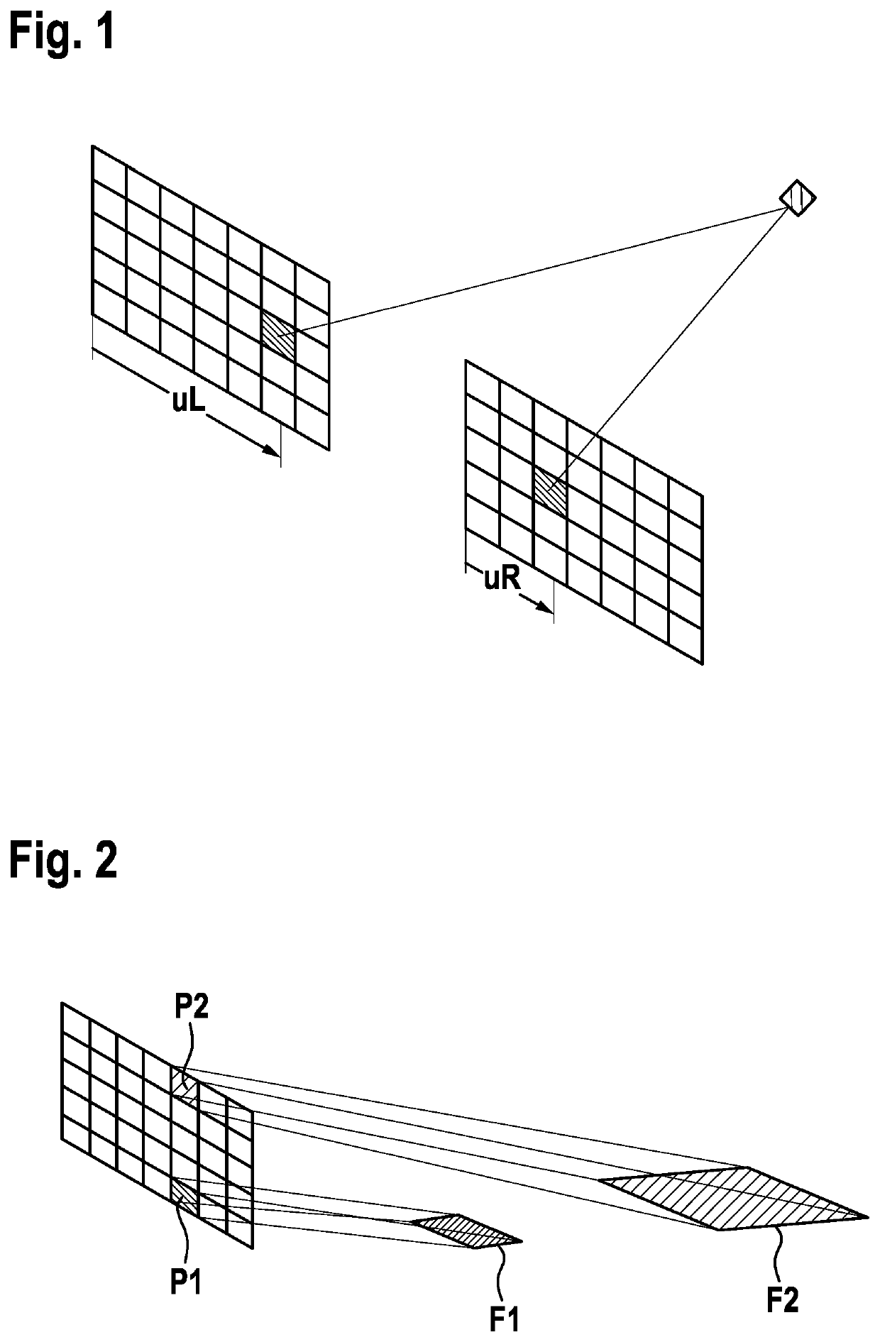
[0041]When a surface area is viewed through a camera having discrete image points (“pixels”), the surface area viewed through a pixel increases in size with increasing distance, as basically shown in FIG. 2. A pixel assumes the average color value and intensity value of the surface area that it represents. Superimposing patterns in different orders of magnitude in terms of geometry and values makes possible a recognizability on different scales, as will be explained in greater detail below.

[0042]A scale is defined by the size of the geometric surface area that it fills with a value. Fo...


PUM


Abstract

A distance measuring element including: at least one first subpattern having a nonrepeating structure of values in a defined first value range; and at least one second subpattern, which, in comparison with the first subpattern, has a non-repeating structure of values in a second value range, the second subpattern having no values in the defined first value range, the at least two subpatterns being superimposed by summing over a defined surface area to form a surface pattern; the minimum distance between the values of the second value range being greater than the maximum value of the first value range.

Description

FIELD[0001]The present invention relates to a distance measuring element. Moreover, the present invention relates to a method for manufacturing a distance measuring element. The present invention also relates to a device for manufacturing a distance measuring element. In addition, the present invention relates to a computer program product.BACKGROUND INFORMATION[0002]When distances are measured by stereoscopy, two lenses are used to view two images of a scene captured by spatially offset cameras. Within the images, points are identified which belong to the same object in space. Due to the spatial offset of the cameras, a point in space is projected onto different coordinates uL of a left sensor plane and uR of a right sensor plane. The horizontal offset of coordinates uL and uR of an identified point in both images is referred to as disparity d=uL−uR, the disparity being a measure of the distance of the point from the observer. A basic representation of the principle of stereoscopic...

Claims


Application Information

Patent Timeline
Patent Type & Authority Patents(United States)
IPC IPC(8): G01B11/02H04N13/239G06K19/06
CPCG01B11/026G06K19/06056H04N13/239G06K19/06037G06K19/06046
Inventor SCHAEFER, FRANK-RENE
Owner ROBERT BOSCH GMBH
Why Eureka
Try Eureka