Estimating apparatus

a technology of turning radius and estimating apparatus, which is applied in the direction of vehicle position/course/altitude control, process and machine control, instruments, etc., can solve the problems of delay in the change of sensor output, sudden change of yaw rate, and travel trajectory estimation, so as to reduce the accumulation of steering angle errors, and improve the detection accuracy

Active Publication Date: 2021-10-26
DENSO CORP
View PDF15 Cites 1 Cited by
  • Summary
  • Abstract
  • Description
  • Claims
  • Application Information

AI Technical Summary

Benefits of technology

[0008]The present disclosure provides a technique of achieving accurate travel trajectory estimation based on odometry information in any situation.
[0010]According to such a configuration, the estimate of the turning radius is calculated mainly based on the yaw rate having good detection accuracy if the yaw rate is low, and mainly based on the steering angle of good responsiveness if the yaw rate is high. Therefore, accumulation of errors included in the steering angle can be minimized on a straight road or the like having a low yaw rate, and occurrence of errors based on the yaw rate of poor responsiveness can be minimized on a curved road or the like having a high yaw rate. As a result, an accurate estimate of a turning radius can be obtained in any situation regardless of the yaw rate, and an accurate travel trajectory can further be calculated from the estimate of the turning radius.

Problems solved by technology

It has been found that travel trajectory estimation may include an error of disagreeing from the actual trajectory in the event that the yaw rate changes abruptly as a result of thorough study conducted by the inventor.
This error is attributed to the delay in the change of the sensor output in response to the operation of the steering wheel.
The abrupt change in the yaw rate may occur not only due to steering wheel operation but also due to sudden braking, uneven road surfaces, or the like during straight traveling.

Method used


Image

  • Estimating apparatus
  • Estimating apparatus
  • Estimating apparatus

Examples


Embodiment Construction

[0022]An embodiment will be described with reference to the drawings according to the present invention.

1. Configuration

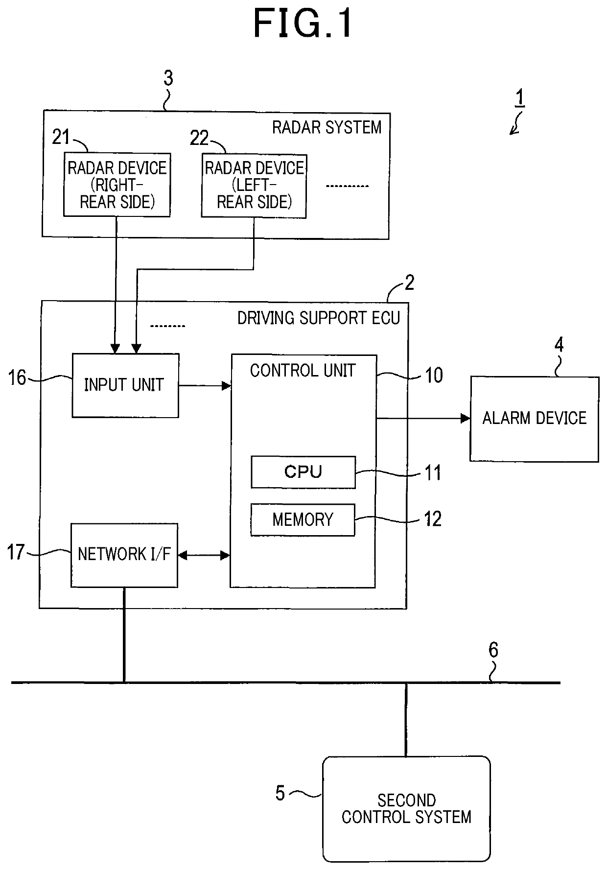
[0023]FIG. 1 shows an on-vehicle system 1 of the present embodiment which includes a driving support ECU 2, a radar system 3, an alarm device 4, and another control system 5. In the present embodiment, the on-vehicle system 1 is mounted to a vehicle that is a four-wheeled vehicle. The vehicle equipped with the on-vehicle system 1 is hereinafter also referred to as an own vehicle.

[0024]The radar system 3 includes a plurality of radar devices 21, 22, . . . . As the plurality of radar devices, the present embodiment at least includes a right-rear radar device 21 provided to a right-rear surface of the vehicle and a left-rear radar device 22 provided to a left-rear surface of the vehicle. The right-rear radar device 21 acquires information on objects present on the right side and the right-rear side of the vehicle. The left-rear radar device 22 acquires information on ...


PUM


Abstract

An odometry acquiring unit acquires odometry information including a yaw rate applied to a vehicle and a steering angle of the vehicle. An estimate calculating unit calculates an estimate of a turning radius based on the steering angle and the yaw rate acquired by the odometry acquiring unit. A change rate calculating unit calculates a yaw change rate representing a degree of change in the yaw rate acquired by the odometry acquiring unit. A contribution adjusting unit makes an adjustment of decreasing a contribution of the yaw rate and increasing a contribution of the steering angle, to calculation of an estimate performed by the estimate calculating unit, as the yaw change rate increases.

Description

CROSS REFERENCE TO RELATED APPLICATION[0001]This application is the U.S. national phase of International Application No. PCT / JP2017 / 005970 filed Feb. 17, 2017 which designated the U.S. and claims priority to Japanese Patent Application No. 2016-28242 filed Feb. 17, 2016, the entire contents of which are hereby incorporated by reference.TECHNICAL FIELD[0002]The present disclosure relates to a technique for estimating a turning radius of a vehicle from odometry information.BACKGROUND ART[0003]A technique that a position or a travel trajectory with respect to a traveling path of an own vehicle is estimated using odometry information of the own vehicle such as a vehicle speed, a yaw angle, and a steering angle without using an external observation sensor such as a GPS apparatus or a camera is known.[0004]The travel trajectory estimation involves use of a turning radius which is one of necessary pieces of information for the estimation. The turning radius can be calculated based on detec...

Claims


Application Information

Patent Timeline
Patent Type & Authority Patents(United States)
IPC IPC(8): B60W40/114B60W40/06G05D1/02G08G1/16
CPCB60W40/114B60W40/06G05D1/0212B60W2520/06B60W2520/14B60W2554/80G05D2201/0213B60W40/072B60W40/10G08G1/16B60W2552/30B60W2540/18B62D15/025B60W30/18145B60W30/045B60W2520/10
Inventor SHIMIZU, NAOTSUGU
Owner DENSO CORP
Why Eureka
Try Eureka