Radar detector for monitoring of bodily functions

a technology for bodily functions and detectors, applied in the direction of sensors, measuring/recording heart/pulse rate, reradiation, etc., can solve the problems of weak signals, limited spatial range, system interference, etc., to improve spatial accuracy and resolution, small and flexible, and improve the effect of sensitivity in remote detection

Active Publication Date: 2021-11-02
RAYTELLIGENCE AB
View PDF24 Cites 0 Cited by
  • Summary
  • Abstract
  • Description
  • Claims
  • Application Information

AI Technical Summary

Benefits of technology

[0007]It is an object of the invention to overcome, or at least partly overcome, one or more of the above-identified limitations of the prior art. In particular, it is an object to improve the spatial accuracy and resolution in remote detection of bodily functions. It is also an object to improve the sensitivity in remote detection of bodily functions. It is a further object to provide high-sensitivity detectors or detector systems that are small and flexible with respect to placement.

Problems solved by technology

These systems have the drawbacks that they need to be carried and require batteries.
Thus, these systems are subject to interference with other technologies allocated within the same frequency band, such as Global Positioning System, TV, Wireless Local Area Network, and military radio equipment.
This typically leads to limited spatial ranges and weak signals.
Further, there is a tradeoff between sampling frequency and position accuracy of the target, which in turn means a limited performance of a UWB impulse-radar systems.
Further, the short pulses are also very hard to generate in a controlled and consistent manner, and the spread in the spectrum may vary between pulses in the UWB impulse-radar system.
The abovementioned monitoring systems typically require cabling for power supply, which complicates the setting up and limits the placement of the systems.
However, the abovementioned monitoring systems are typically limited to mountings on walls ceilings, where electric contacts typically are not readily available and manual adjustments are difficult.

Method used


Image

  • Radar detector for monitoring of bodily functions
  • Radar detector for monitoring of bodily functions
  • Radar detector for monitoring of bodily functions

Examples


Embodiment Construction

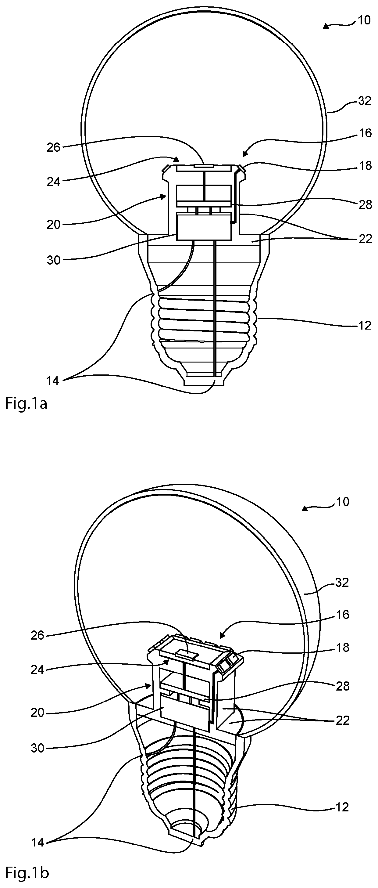
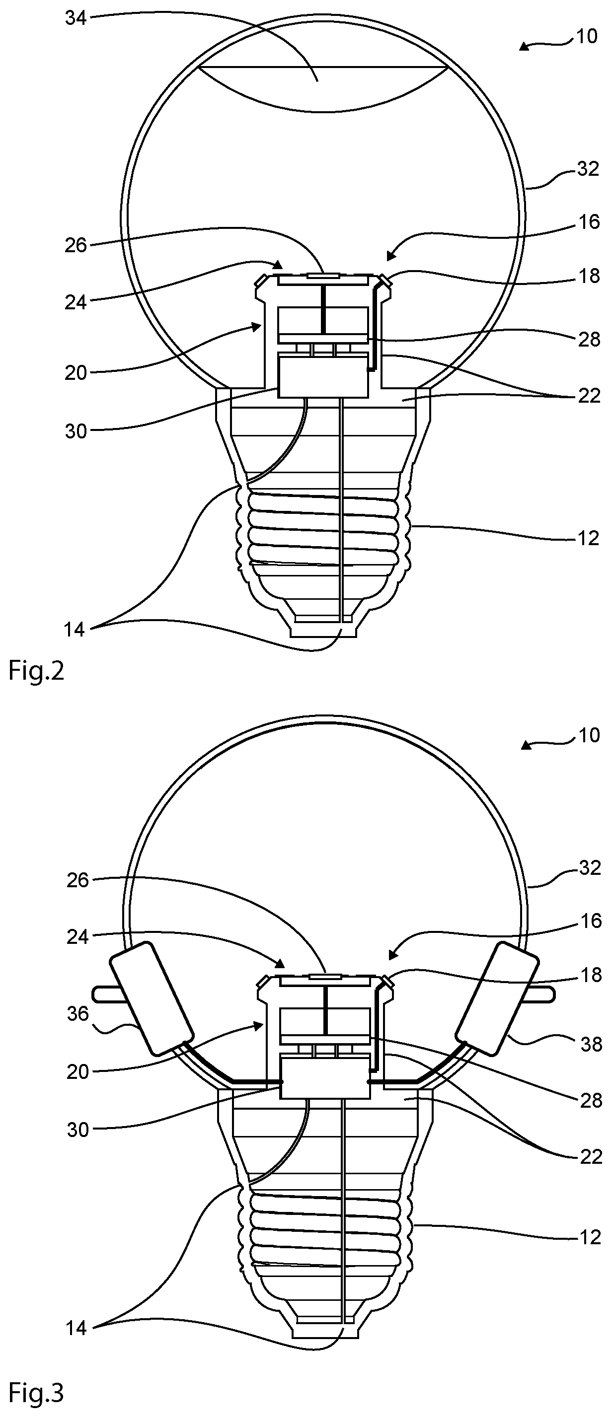
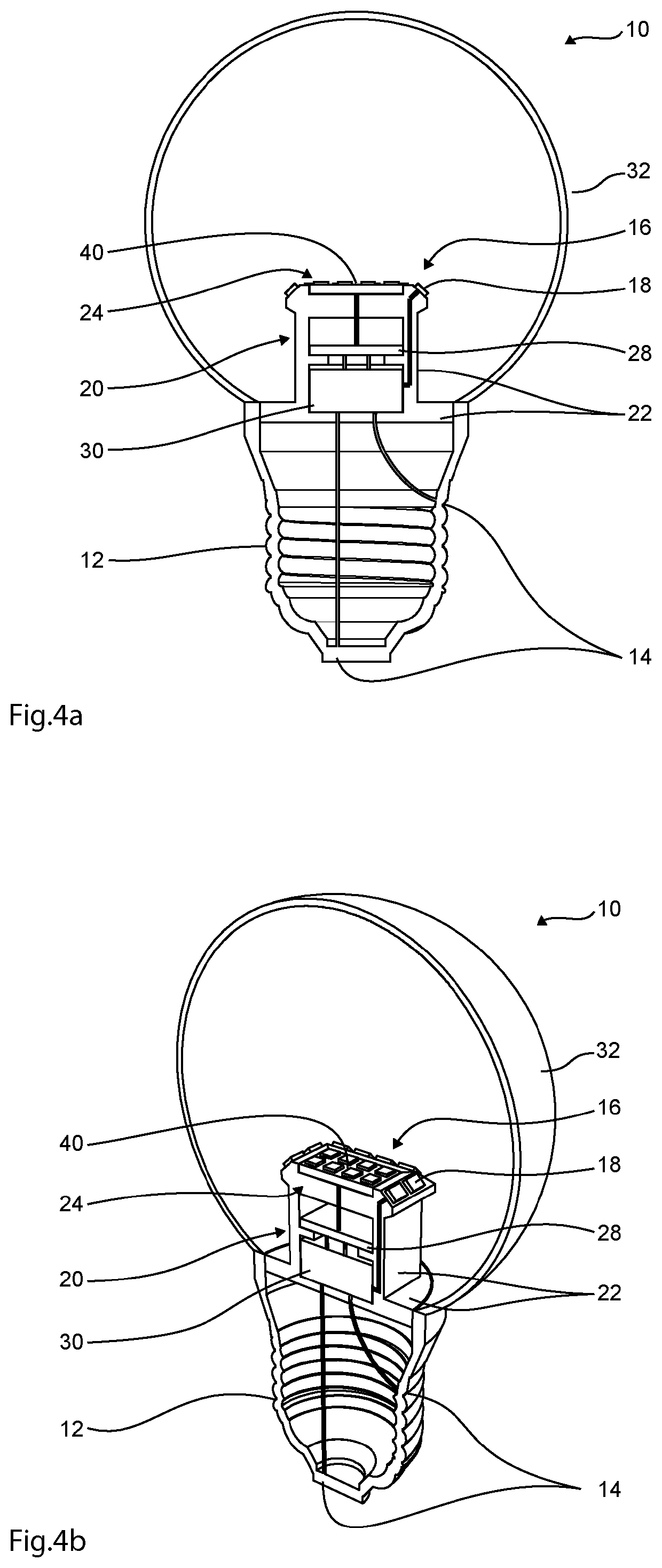
[0063]With reference to FIGS. 1a and 1b, a lamp 10 is illustrated having a base 12 that can fit in a socket of a light-fixture (not shown). In the shown embodiment, the base 12 is an Edison screw. In other embodiments, bases configured for other socket are used, such as bayonet mounts and Bi-pin connectors. The base 12 has an electric contact that can establish an electric connection with a socket. The lamp has a light emitter 16 in the form of several Light-Emitting Diodes (LEDs) 18. The diodes are directed outward so that they illuminate the surroundings of the lamp 10.

[0064]The lamp 10 also has a detector 20 with a support structure 22 that is connected to and supported by the base 12. A CW radar module 24 is supported by the support structure 22. The radar module 24 has an antenna 26 that is oriented to emit microwaves in direction away from the base 12. The radar module 24 radiate microwaves at maximum power in this direction and receives microwaves at maximum power gain from t...


PUM


Abstract

A detector (210) for indicating bodily functions of a person in the surroundings of the detector (210) is proposed. The detector (210) comprises a support structure and a Continuous-Wave (CW) radar module (214) supported by the support structure. The radar module (214) is configured to emit microwaves and receive microwaves that have been reflected in the surroundings of the detector (210), wherein the radar module (214) is configured to determine data indicating bodily functions from microwaves reflected on a person. The detector (210) further comprises a collimator (216) supported by the support structure and configured for collimating the emitted microwaves in one spatial direction, or towards a plane.

Description

CROSS-REFERENCE TO RELATED APPLICATION[0001]This application is the National Phase, under 35 U.S.C. § 371(c), of International Application No. PCT / SE2016 / 051236, filed Dec. 9, 2016, which claims priority from SE 1551621-4, filed Dec. 10, 2015, and SE 1651423-4, filed Oct. 28, 2016. The disclosures of all of the referenced applications are incorporated herein by reference in their entireties.FEDERALLY SPONSORED RESEARCH OR DEVELOPMENT[0002]Not ApplicableTECHNICAL FIELD[0003]The invention relates to detectors for remotely monitoring of bodily functions.BACKGROUND ART[0004]In many healthcare situations, the ability to monitor and detect bodily functions or vital life signs, such as heart beats, are of great importance. There are systems based on wearable devices that are attached to the body, such as watches, wrist bands, or integrated sensors in clothing. These systems have the drawbacks that they need to be carried and require batteries. Thus, there is a need for monitoring systems t...

Claims


Application Information

Patent Timeline
Patent Type & Authority Patents(United States)
IPC IPC(8): G01S13/88A61B5/024A61B5/0507A61B5/08A61B5/11G01S13/02F21K9/232
CPCG01S13/88A61B5/02444A61B5/0507A61B5/0816A61B5/11G01S13/02A61B2560/0406F21K9/232A61B5/113F21V33/0052G01S13/0209G01S13/50
Inventor VIBERG, PER-ARNENILSSON, EMIL
Owner RAYTELLIGENCE AB
Why Eureka
Try Eureka