
Method for hanging PV modules

a pv module and pv module technology, applied in the direction of photovoltaics, electrical equipment, semiconductor devices, etc., can solve the problems of the cost of bifacial pv modules reaching the point where they can be produced, and achieve the effect of reducing the strength requirements of the overall pv module mounting structure, preventing damage in high winds, and reducing the swinging movement of modules

Active Publication Date: 2021-11-02
MCCABE JOSEPH
View PDF67 Cites 0 Cited by
  • Summary
  • Abstract
  • Description
  • Claims
  • Application Information

AI Technical Summary

Benefits of technology

The invention aims to prevent damage to PV modules in high winds and reduce the overall mounting structure strength requirements. It also aims to reduce soiling of the modules, potential fire spread, and the cost of materials and labor. The invention achieves these goals by reducing the swinging movement of modules, separating them from each other to prevent damage, and utilizing innovative technologies such as reducing module glass thickness, simplifying interconnection wiring, and increasing module installation verticality. The invention also reduces land area requirements and associated civil engineering costs. The invention achieves a reduction in electrical equipment cost and maintenance issues due to reduced peak sunlight and warranty limitations.

Problems solved by technology

Currently the cost of bifacial PV modules have reached the point where they can be produced for only a few pennies more than conventional one sided PV modules.

Method used


Image

  • Method for hanging PV modules
  • Method for hanging PV modules
  • Method for hanging PV modules

Examples


Embodiment Construction

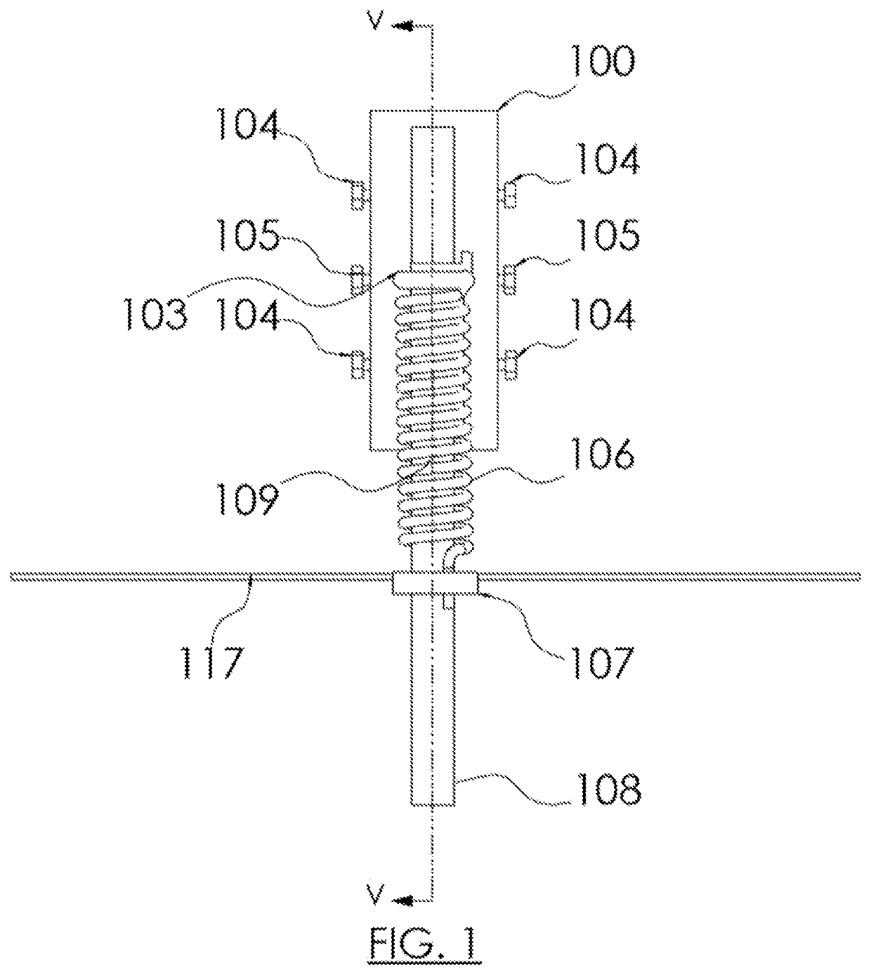
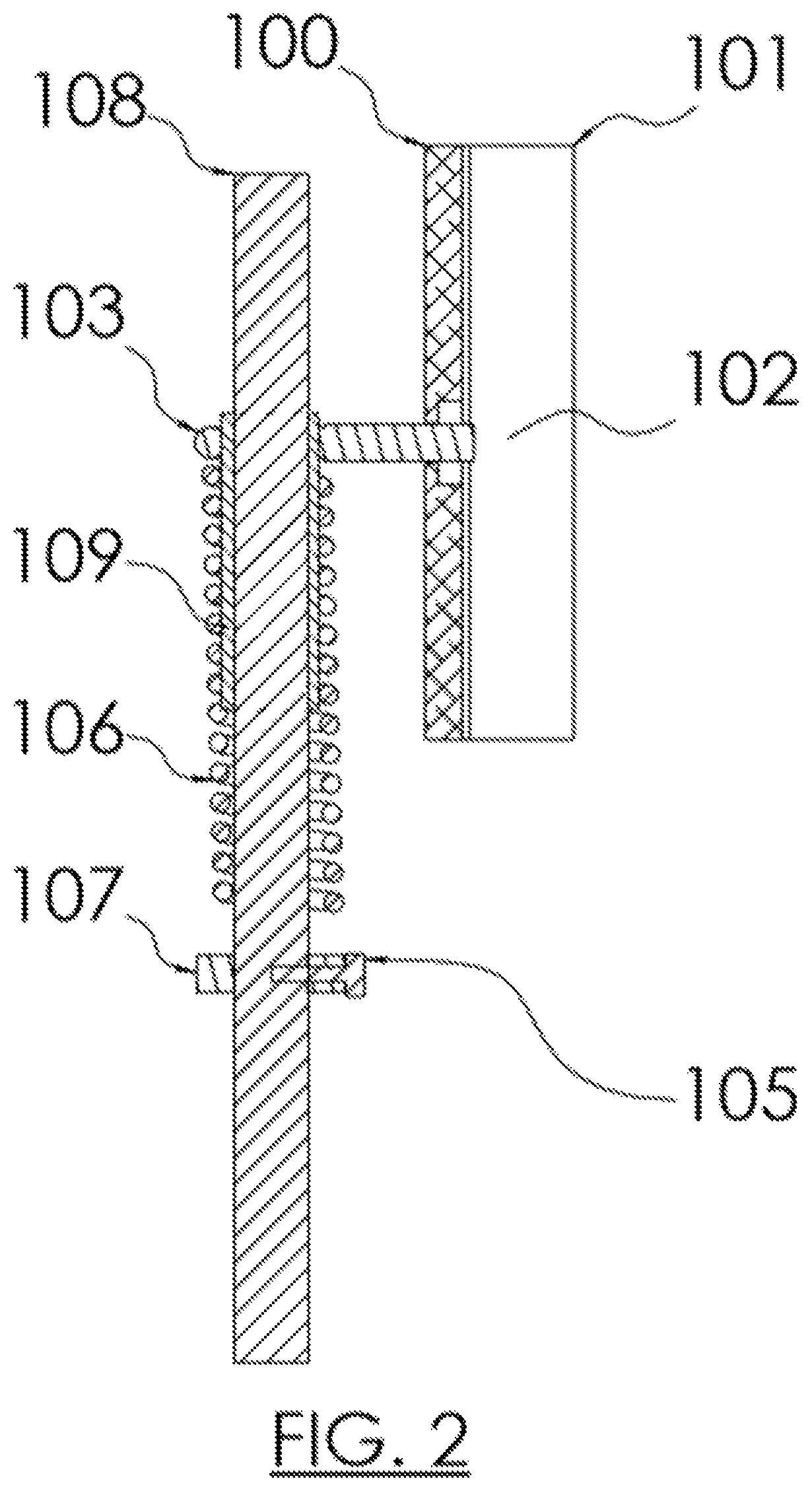
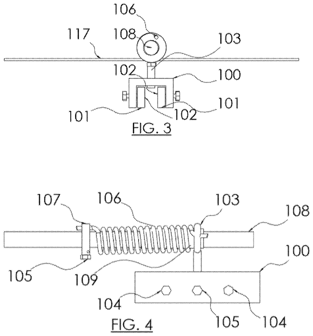
[0107]This invention is vertically hanging PV modules and allowing them to sway and swing with the wind. There are no motors or linkages connecting or between PV modules. The vertical orientation of the no-wind and low-wind situation is unique in that it allows for solar energy to be captured on both sides of the PV modules, in the morning and evening for a north-south orientation. This is instead of one side facing the equator at an angle to the horizontal in typical orientations. PV modules have thought to need a rigid structure but with this disclosure, a rigid structure is not required. This design reduces the need for an expensive metal PV module frame, reduces electrical balance of systems costs and potentially allows for PV modules designed with less or no glass as well as other reduced costs of operating solar electric systems including operating and maintenance costs.

[0108]The invention is unique in that it isn't a tracker, modules are not linked to each other. There is no ...


PUM


Abstract

The invention relates to a photovoltaic (PV) module or array of PV modules which are pivotally mounted from an upper edge and thus designed to hang under the force of gravity and to swing about the upper edge responsive to wind. The invention further includes various motion damping systems calibrated to limit or slow said swinging motion. The invention further includes a preferred mounting means comprising at least one ring or cylinder or sleeve or hinge attached to the upper edge of PV modules with a spring calibrated to limit or dampen the swinging motion.

Description

CROSS REFERENCE TO RELATED APPLICATIONS[0001]This application claims the benefit of U.S. Provisional Application filed May 18, 2018, Application No. 62 / 673,840 filed by Joseph McCabe with the title “Method for hanging PV modules”.[0002]U.S. Pat. No. 10,269,271 White, Apr. 23, 2019, Display mounting system and method[0003]U.S. Pat. No. 10,152,903 Dalton, Dec. 11, 2018, Swinging sign apparatus[0004]U.S. Pat. No. 10,110,161 Lerner, et al., Oct. 23, 2018, Systems and methods for applying flexible solar panels to flexible underlying membranes[0005]U.S. Pat. No. 10,090,799 Dalland, et al., Oct. 2, 2018, Tensioned sheet-metal based solar panels and structures for supporting the same[0006]U.S. Pat. No. 9,988,776 Holland, et al., Jun. 5, 2018, Wind screens for photovoltaic arrays and methods thereof[0007]U.S. Pat. No. 10,008,134 Pura, et al., Jun. 26, 2018, Outdoor sign system and a method of using the same[0008]U.S. Pat. No. 9,916,783 Ashworth, et al., Mar. 13, 2018, Banner support assembly...

Claims


Application Information

Patent Timeline
IPC IPC(8): H02S20/30H02S30/10H02S20/32
CPCH02S20/30H02S20/32H02S30/10Y02E10/50H02S20/00H01L31/042H02S30/00
Inventor MCCABE, JOSEPH
Owner MCCABE JOSEPH
Learn More