Contraction device having heating control

a technology of a compression device and a control panel, which is applied in the direction of induction heating, induction heating control, induction heating apparatus, etc., can solve the problems of excessive long inductive heating, errors can occur, and the shrink-fit devices disclosed up to this point are not optimally automated

Active Publication Date: 2021-11-02
HAIMER
View PDF15 Cites 0 Cited by
  • Summary
  • Abstract
  • Description
  • Claims
  • Application Information

AI Technical Summary

Benefits of technology

[0009]The use of the present inductance as a measure for the current temperature of the sleeve part has the significant advantage that the interference variables such as color, quality, and cleanliness of the surface of the sleeve part, which had previously distorted measurements, are completely suppressed. In comparison to previously used electrical values such as the measurement or calculation of the electrical energy that has been applied up to a certain point in time, the measurement of the present inductance has the advantage that it is significantly more precise. Consequently, the shrink-fit chuck is not always heated to the maximum value and for a maximum time, but instead, power is induced in a customized way, which prevents damage to the shrink-fit chuck and may accelerate the re-cooling.Other Embodiment Options
[0034]Alternatively, it has turned out to be particularly advantageous to provide the shrink-fit device with a battery, which supplied with power. Such a device can also be highly mobile. The logical choice in this case is to provide a carriage, for example in the form of a very easily maneuverable hand truck, which carries the battery in the lower region, for example a vehicle battery, and carries the shrink-fit device in its upper region.

Problems solved by technology

The shrink-fit devices that have been disclosed up to this point are not optimally automated.
Errors can occur such as an excessively long inductive heating of the sleeve part of a tool holder.
This can result in an overheating of the sleeve part of the tool holder.
This can result in a disadvantageous change in structure.
If the sleeve part is not immediately discarded, there is in any case a danger that it will develop cracking if it is overheated multiple times.
The contacting sensors have their own problems as well.
It is designed so that a possibly present leakage field induces electrical current in it, thus drawing energy from the leakage field and thereby weakening the field.
This is because the leakage field lines cannot penetrate into this deeper-lying recess in which the power semiconductor component is positioned.
This is because it is dangerous to work with a mobile shrink-fit device that is nearly resting freely somewhere in the vicinity of the machine tool, without somehow being reliably fastened.

Method used


Image

  • Contraction device having heating control
  • Contraction device having heating control
  • Contraction device having heating control

Examples


Embodiment Construction

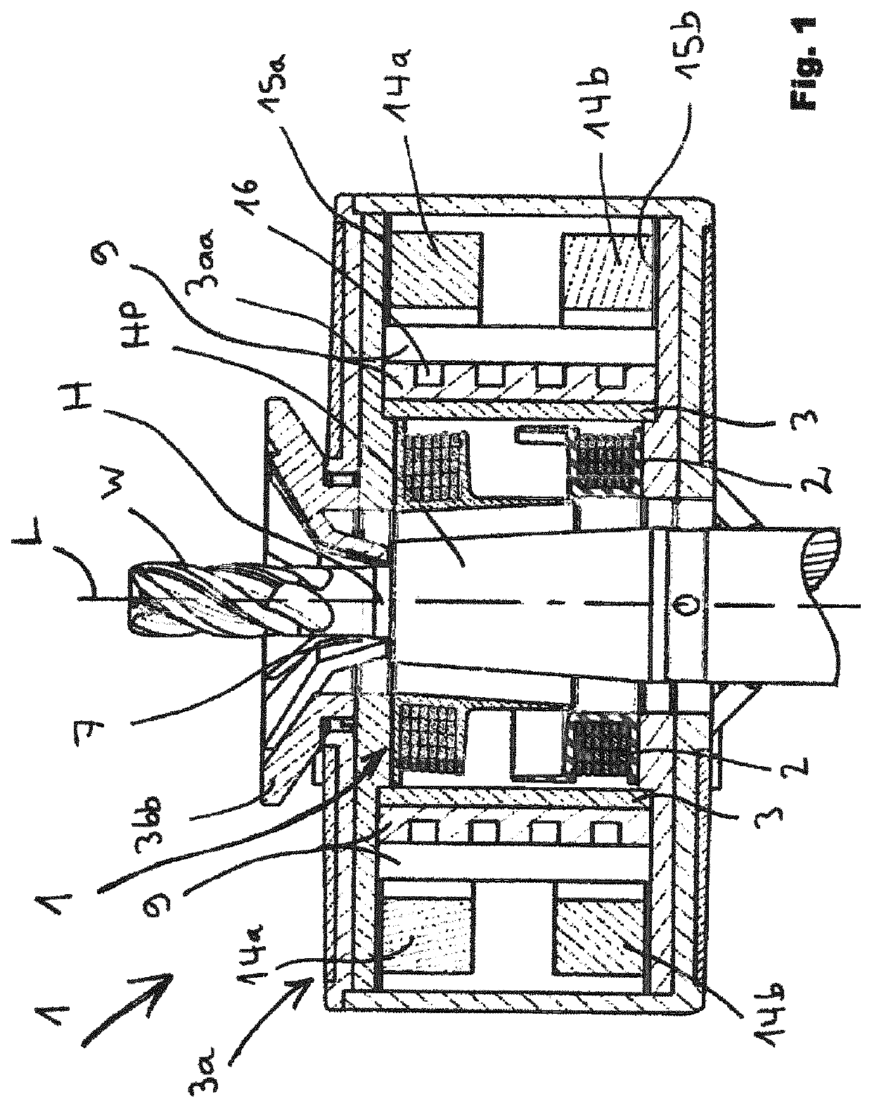
[0047]FIG. 1 shows a first basic overview of the device according to the invention.

[0048]Basic Principle of Inductive Shrink-Mounting and Removal

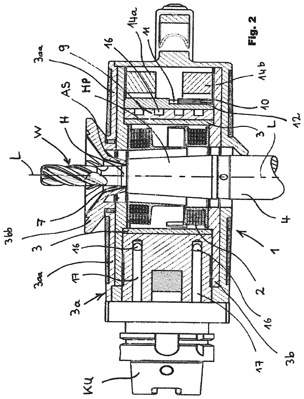
[0049]The drawing here clearly shows the induction coil 1 with its internal windings 2 into the center of which a tool holder 4 is slid in order to shrink-mount or remove the holding shaft H of a tool W in the sleeve part HP. The basic function on which the shrink-mounting and removal are based is described in greater detail in the German patent application DE 199 15 412 A1. The content thereof is hereby made the subject of this application.

[0050]The Shielding of the Induction Coil with Magnetically Conductive and Electrically Nonconductive Means

[0051]The present invention places high demands on the shielding of the induction coil, even on the conventional shielding, which, by its very nature, is already known.

[0052]On its outer circumference, the induction coil is provided with a first casing 3 composed of electrically nonconductive and ma...


PUM

PropertyMeasurementUnit
frequencyaaaaaaaaaa
radial distanceaaaaaaaaaa

Abstract

The invention relates to a method for monitoring the temperature of the sleeve part of a tool holder, which sleeve part is inserted into the induction coil of a contraction device, wherein the instantaneous inductance of the induction coil is measured during the inductive heating and the current supply to the induction coil is influenced if the instantaneous inductance approaches, reaches, or exceeds a specified value.

Description

BASIC SUBJECT OF THE INVENTION[0001]The invention relates to a shrink-fit device according to the preamble to claim 1.PRIOR ART[0002]Shrink-fit devices for shrink-mounting and removal of tool shafts in tool holders have been known for quite some time. Originally, such shrink-fit devices were operated with a gas burner or hot air, by means of which the sleeve part of the tool holder was heated in order to cause it to expand enough that it can accommodate or release a snugly-seated tool shaft. Recent times have seen widespread use of shrink-fit devices in which the respective tool holder is heated with the aid of an induction coil. This has significantly accelerated the shrink-fitting process, has made it more efficient and easy to use, and has therefore contributed to its widespread use.[0003]The first shrink-fit device that was usable for practical applications is described in the patent literature by the German patent application DE 199 15 412.[0004]The shrink-fit devices that have...

Claims


Application Information

Patent Timeline
Patent Type & Authority Patents(United States)
IPC IPC(8): H05B6/06B23P11/02H05B6/10H05B6/38H05B6/40H05B6/14
CPCH05B6/06B23P11/027H05B6/101H05B6/14H05B6/38H05B6/40H05B6/10
Inventor PODHRÁZKÝ, ANTONÍN
Owner HAIMER
Why Eureka
Try Eureka