Pulling tool for use in a wellbore and/or tubing and a propulsion module of a pulling tool

a technology for pulling tools and wellbores, which is applied in the direction of gearing, mechanical equipment, borehole/well accessories, etc., can solve the problems of no pulling tool that is specially designed, fiber optic cable is very thin and weak, and the problem of affecting the performance of the pulling tool is very difficult to solve, so as to achieve the effect of high gear ratio, high gear ratio and robustness and efficiency

Active Publication Date: 2021-11-09
WELL CONVEYOR AS
View PDF13 Cites 0 Cited by
  • Summary
  • Abstract
  • Description
  • Claims
  • Application Information

AI Technical Summary

Benefits of technology

[0011]Another object of the invention is to be able to construct a pulling tool of smaller diameter than the pulling tools currently available in the market. Through the present invention a small-sized, lightweight, high performance propulsion unit which is preferably battery-operated is obtained.
[0032]In the present invention, a high efficiency, high RPM, low torque, submergible brushless motor can be used which exhibits good moisture resistance and wear resistance and does not lose power and efficiency over time. This is enabled through the use of a gear system inside the propulsion wheel that includes an internally toothed gear system in the form of a harmonic gear or a two-ring compound epicyclic gear having a rated transformer ratio and an output torque that is significantly larger than what can be achieved with an ordinary planetary gear of the same size.

Problems solved by technology

In itself, a fiber optic cable is very thin and weak.
Common to all these cables are that they are very lightweight and a bit flexible, which present some challenges when they are to be installed in horizontal wells.
Currently, no pulling tool exists that is specially designed for these applications.
Similarly to a fiber optic cable, the same challenges are encountered when a slick line is to be run into horizontal wells.
Due to the limited rigidity of the slick line, it cannot be pushed very far into horizontal wells.
Such a system is technically complex and not very efficient.
Such systems present a challenge in that the gear ratio is not sufficiently high to allow the use of a high efficiency, brushless permanent magnet motor operating at a relatively high RPM.
However, there is a limitation on how small a planetary gear can be made since such a gear includes a number of components located inside each other, each of which needs to resist the torque applied.
In addition, the achievable gear ratio is relatively low.

Method used


Image

  • Pulling tool for use in a wellbore and/or tubing and a propulsion module of a pulling tool
  • Pulling tool for use in a wellbore and/or tubing and a propulsion module of a pulling tool
  • Pulling tool for use in a wellbore and/or tubing and a propulsion module of a pulling tool

Examples


Embodiment Construction

[0062]The invention will now be explained in more detail when a compound split ring epicyclic gear is used, with reference to the drawings:

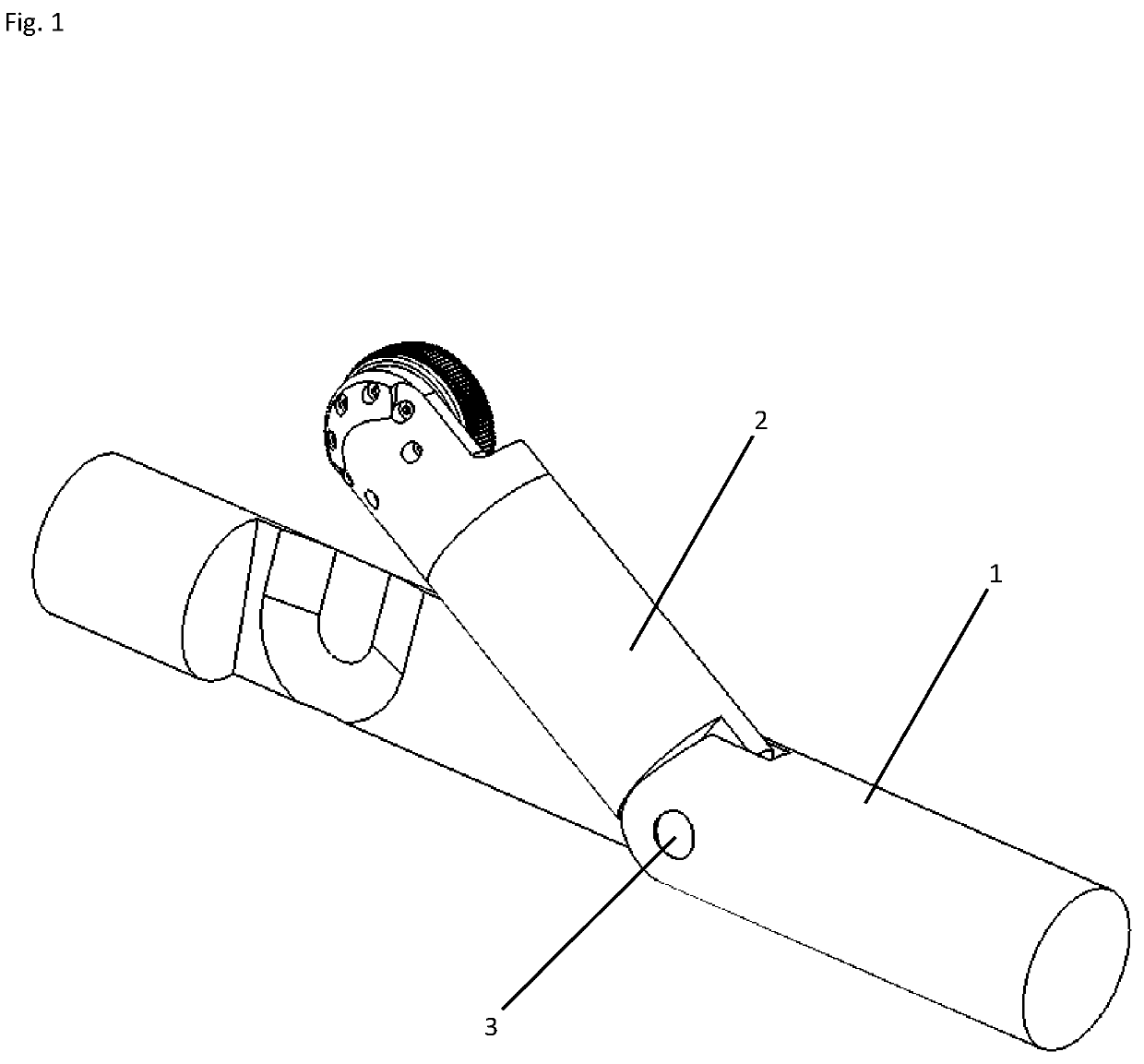
[0063]FIG. 1 shows a perspective view of an embodiment of a pulling assembly according to this invention. The pulling assembly comprises a main section 1 supporting a complete propulsion arm 2. Complete propulsion arm 2 is connected to main section 1 via a hinge joint 3 by way of which complete propulsion arm 2 can be tilted outwards.

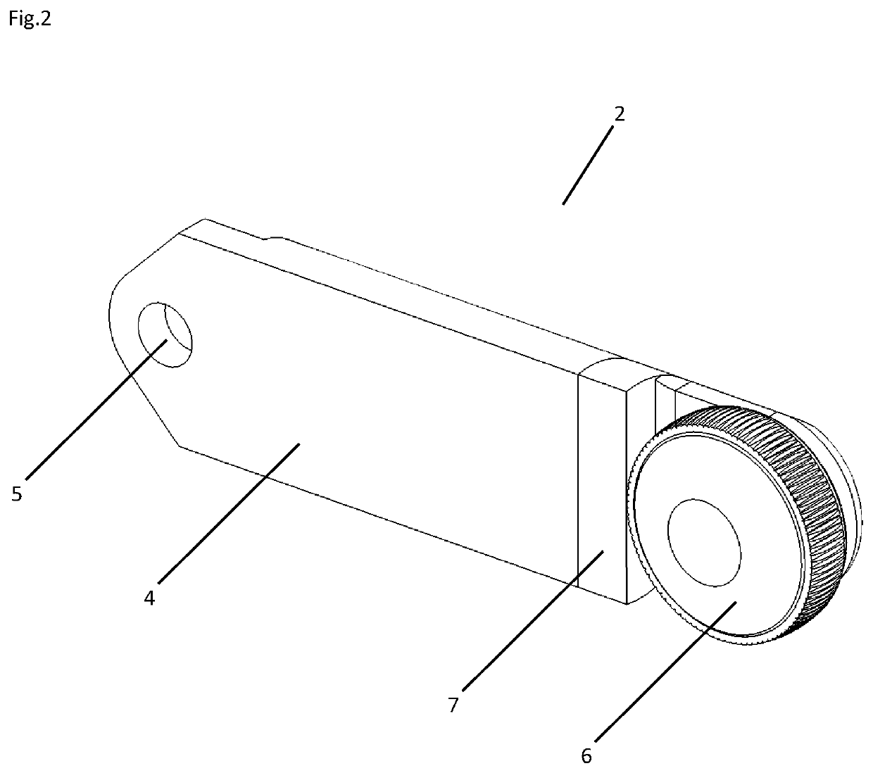
[0064]FIG. 2 shows complete propulsion arm 2 comprising a rear arm body 4, a pivoting hole 5, the drive mechanism of FIG. 3, a complete propulsion wheel 6 and a front arm body 7.

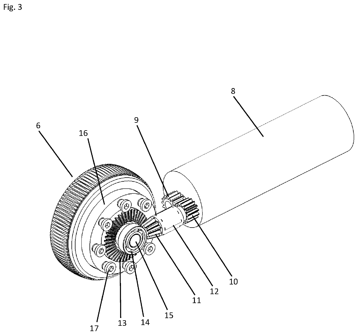
[0065]FIG. 3 shows the drive mechanism comprising a motor 8, a straight gear 9 fixed to the drive shaft of the motor driving a straight gear 10. Straight gear 10 is connected to an angular gear 11 supported in front arm body 7 (FIG. 2) by way of a bearing 12. Angular gear 11 is connected to an angular gear 13 being part of the complete propul...


PUM


Abstract

A pulling tool for use in a wellbore or tubing for pulling cable includes a propulsion module having a main section and a propulsion arm hinged to the main section. The propulsion arm includes a complete propulsion wheel with a gear system. An electric motor is configured to drive the complete propulsion wheel via the gear system. The gear system may include a harmonic gear or a compound split ring epicyclic gear.

Description

[0001]This invention relates to a pulling tool and to a propulsion module of a pulling tool used for pulling itself and other equipment into wellbores and tubing.BACKGROUND OF THE INVENTION[0002]Wellbores and tubing typically include long vertical and horizontal runs. In many wells there is a need for installing a fiber optic cable in order to obtain real-time measurements of flow, pressure, and temperature, among other things. In itself, a fiber optic cable is very thin and weak. Therefore, several types of claddings are used for protecting the fiber optic cable such as metal, Kevlar, or carbon rods. Common to all these cables are that they are very lightweight and a bit flexible, which present some challenges when they are to be installed in horizontal wells.[0003]Since a fiber optic cable is a signal cable only, the pulling tool needs to be battery operated. Therefore, it is essential that the pulling tool is as efficient and lightweight as possible to limit the necessary power c...

Claims


Application Information

Patent Timeline
Patent Type & Authority Patents(United States)
IPC IPC(8): E21B23/14E21B4/00E21B4/18E21B23/00
CPCE21B4/006E21B4/18E21B23/001E21B23/14E21B23/00F16H1/28F16H3/42E21B17/1057F16H49/001F16H1/14F16H37/041F16H2001/2872
Inventor FUGLESTAD, KENNETH
Owner WELL CONVEYOR AS
Why Eureka
Try Eureka