
Collimater, radiation detection device, and radiation inspection device

a radiation detection device and collimator technology, applied in the field of collimators, radiation detection devices, radiation inspection devices, can solve problems such as detection accuracy degradation, and achieve the effect of compact form and production process

Active Publication Date: 2021-11-23
ANSEEN
View PDF26 Cites 0 Cited by
  • Summary
  • Abstract
  • Description
  • Claims
  • Application Information

AI Technical Summary

Benefits of technology

The invention simplifies the production process and allows for more compact devices by eliminating the need for a light-blocking plate. This results in a collimator, radiation detection device, and radiation inspection device that can be produced in a more efficient and compact way.

Problems solved by technology

When the radiation detection device detects scattered radiation, detection accuracy deteriorates.

Method used


Image

  • Collimater, radiation detection device, and radiation inspection device
  • Collimater, radiation detection device, and radiation inspection device
  • Collimater, radiation detection device, and radiation inspection device

Examples


first embodiment

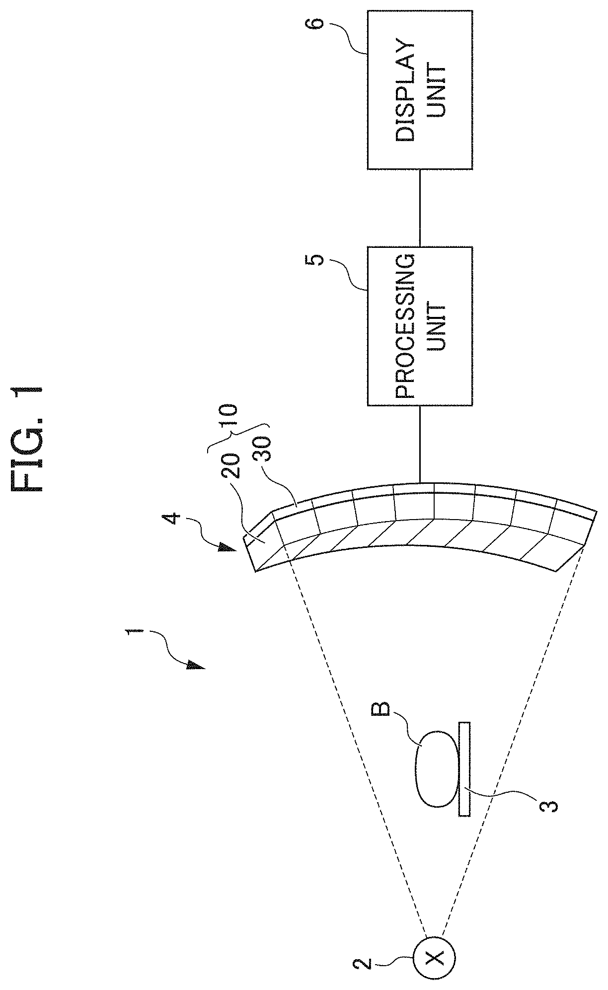
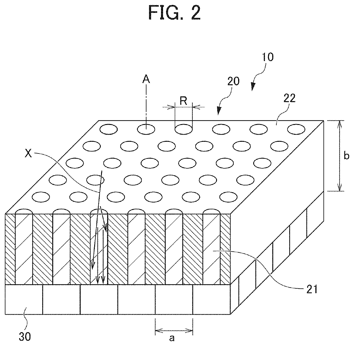
[0036]FIG. 2 is a cross-sectional perspective view of one X-ray detection unit 10 according to a first embodiment. Each X-ray detection unit 10 includes a collimator 20 and a plurality of X-ray detection elements (radiation detection elements) 30.

[0037]The X-ray detection elements 30 are arranged at intervals (pitch) of about 0.1 to 2.00 mm. The X-ray detection elements are arranged in correspondence with respective X-ray transmission sections 21 provided to the collimator 20 described below.

[0038]The X-ray detection elements 30 may be of an indirect conversion type or a direct conversion type. An X-ray detection element 30 of an indirect conversion type is composed of a scintillator and an optical sensor such as a photomultiplier, converting incident X-rays into light by the scintillator and converting the converted light into electrical signals by a photoelectric conversion element.

[0039]An X-ray detection element30 of a direct conversion type is composed of a plurality of cadmium...

second embodiment

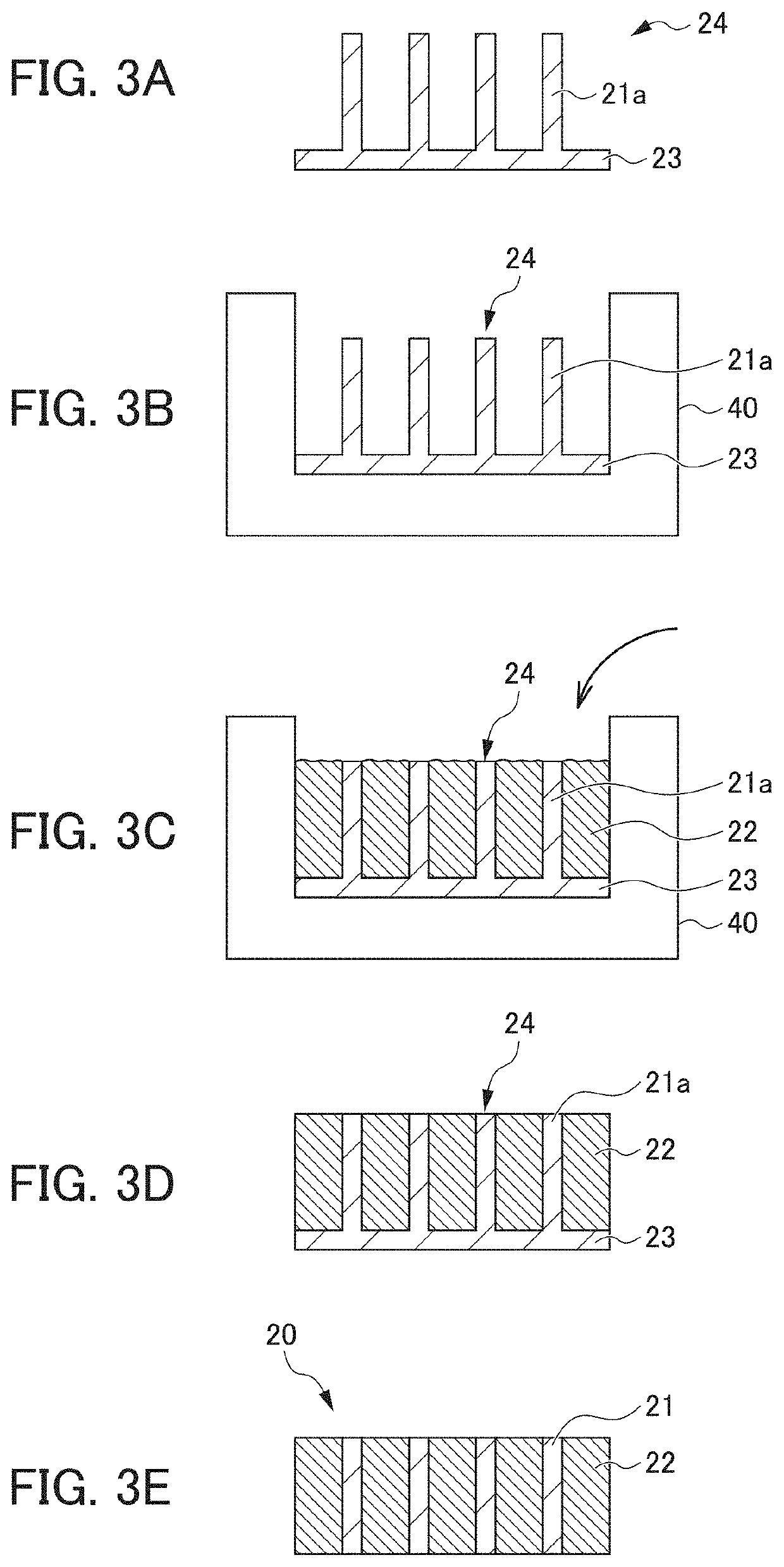
[0080]Next, a second embodiment of the present invention will be described. The second embodiment differs from the first embodiment in terms of the structure and production method of a collimator 120. Since the other aspects are the same as in the first embodiment, description of the same portions is omitted. Tin is used for the X-ray blocking section 22 of the collimator 20 of the first embodiment, but for an X-ray blocking section 122 of the collimator 120 of the second embodiment, mercury, which is a liquid at room temperature, is used.

[0081]FIG. 8 is a drawing describing a method for producing the collimator 120 according to the second embodiment. As shown in FIG. 8C, the collimator 120 of the second embodiment includes a container 150, a liquid X-ray blocking section 122 of mercury enclosed within the container 150, and a plurality of X-ray transmission sections 121 made of a solid material with a lower X-ray blocking rate than the X-ray blocking section 122 such as carbon and ...


PUM


Abstract

Provided are a collimator, a radiation detection device, and a radiation inspection device that are capable of further removing scattered radiation. This collimator 20 comprises: a radiation blocking section 22; and a radiation transmission section 21 that has a lower radiation blocking rate than the radiation blocking section 22, penetrates the radiation blocking section 22, and is solid. The X-ray transmission section 21 of the collimator 20 is solid therefore X-rays on the low-energy side that have been scattered by a subject B in the X-ray transmission section 21 are absorbed, as a result of this collimator 20. Accordingly, there is little noise contained in X-rays detected by a radiation detection element 30 and a high-resolution X-ray image can be obtained.

Description

TECHNICAL FIELD[0001]The present invention relates to a collimator, radiation detection device, and radiation inspection device.BACKGROUND ART[0002]Radiation inspection devices that perform nondestructive testing, such as, for example, X-ray computed tomography (CT) devices, irradiate a subject with radiation and generate a CT image based on the radiation transmitted through the subject.[0003]This kind of radiation inspection device is equipped with a radiation emitting device and a radiation detection device. The radiation irradiated onto the subject is partially scattered inside the subject. When the radiation detection device detects scattered radiation, detection accuracy deteriorates. In order to remove this scattered radiation, the radiation detection device is provided with a collimator.[0004]Collimators are conventionally provided with a plurality of through holes that transmit radiation. When radiation passes through these through holes, radiation that enters a through hole...

Claims


Application Information

Patent Timeline
Patent Type & Authority Patents(United States)
IPC IPC(8): A61B6/00A61B6/03A61B6/10
CPCA61B6/5282A61B6/032A61B6/107A61B6/4291A61B6/03A61B6/06G21K1/025G21K1/02
Inventor MORII, HISASHIOKUNOYAMA, TAKAHARUTAKAGI, KATSUYUKI
Owner ANSEEN
Learn More