Remote vehicle control device, remote vehicle control system, and remote vehicle control method
a remote vehicle control and vehicle control technology, applied in vehicle position/course/altitude control, process and machine control, instruments, etc., can solve the problems of unsatisfactory convenience and operability of remote vehicle control, and achieve the effect of improving convenience and operability in remote control
- Summary
- Abstract
- Description
- Claims
- Application Information
AI Technical Summary
Benefits of technology
Problems solved by technology
Method used
Image
Examples
first example
5-1. First Example
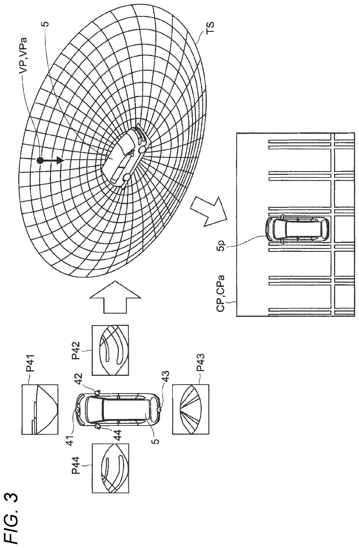
[0089]The mobile terminal 1 may receive images for display (synthetic images) which are output from the image processing device 2, and display the images on the display unit 11. FIG. 4 is a schematic diagram illustrating the mobile terminal 1 displaying a synthetic image CP1 according to a first example.
[0090]FIG. 5 is a schematic diagram illustrating the bird's eye view image CP1 displayed on the mobile terminal 1 according to the first example. As shown in FIG. 5, on the occasion of remotely controlling the vehicle 5, the mobile terminal 1 displays icons and so on which are function images related to remote control on the vehicle 5, on the display unit 11. In other words, on the bird's eye view image CP1, icons and so on which are images of the operation unit 12 are superimposed. The operation unit 12 is disposed according to the position of the image 5p of the vehicle 5 on the bird's eye view image CP1.
[0091]Specifically, on the screen of the display unit 11, fo...
second example
5-2. Second Example
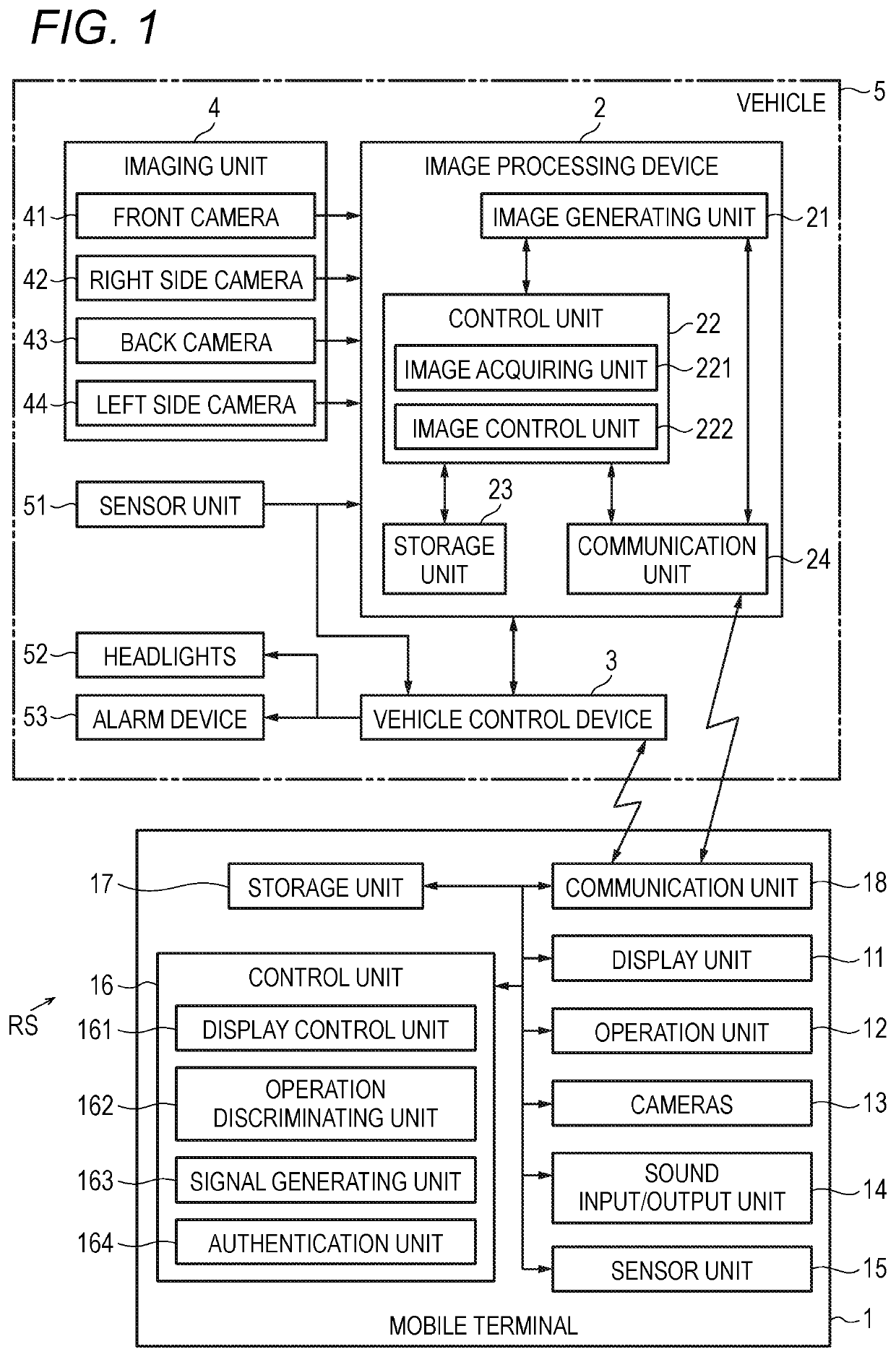
[0112]FIG. 7 is a flow chart illustrating an example of the flow of processing related remote vehicle control according to a second example. The processing which is related to remote control on the vehicle 5 and is performed by the mobile terminal 1 of the second example will be described with reference to FIG. 7.
[0113]For example, if the mobile terminal 1 is operated by the user, and receives a remote control start instruction from the operation unit 12, the processing of the mobile terminal 1 related to remote control on the vehicle 5 is started (“START” of FIG. 7). Remote control on the vehicle 5 is started when the vehicle 5 is stopped.
[0114]Next, the mobile terminal 1 performs confirmation of authentication of the mobile terminal 1 (STEP S201). The authentication unit 164 refers to the specific information for specifying the mobile terminal 1, stored in the storage unit 17 in advance.
[0115]Next, the mobile terminal 1 determines whether the mobile terminal is ...
third example
5-3. Third Example
[0122]FIG. 8 is a schematic diagram illustrating the mobile terminal 1 displaying a synthetic image CP1 and the operation unit 12 according to a third example. The mobile terminal 1 of the third example displays the plurality of icons related to remote control on the vehicle 5, as the operation unit 12, on the screen of the display unit 11, so as to overlap the synthetic image CP1.
[0123]Further, the mobile terminal 1 disposes a numeric-value input section 121 of the operation unit 12 below the synthetic image CP1. The numeric-value input section 121 includes direction indicator icons 121a, a distance input section 121b, and an angle input section 121c. However, the arrangement of the synthetic image CP1 and the numeric-value input section 121 in the vertical direction may be changed.
[0124]As the direction indicator icons 121a, for example, four icons indicating four directions, the front side, the rear side, the left side, and the right side of the vehicle 5 are di...
PUM
 Abstract
Description
Claims
Application Information
 - R&D
- Intellectual Property
- Life Sciences
- Materials
- Tech Scout
- Unparalleled Data Quality
- Higher Quality Content
- 60% Fewer Hallucinations
Browse by: Latest US Patents, China's latest patents, Technical Efficacy Thesaurus, Application Domain, Technology Topic, Popular Technical Reports.
© 2025 PatSnap. All rights reserved.Legal|Privacy policy|Modern Slavery Act Transparency Statement|Sitemap|About US| Contact US: help@patsnap.com


