
Projection display apparatus

Active Publication Date: 2021-11-30
SONY CORP
View PDF17 Cites 0 Cited by
  • Summary
  • Abstract
  • Description
  • Claims
  • Application Information

AI Technical Summary

Benefits of technology

The patent text describes a new projection display apparatus that is designed to be smaller in size. The key to achieving this is by using a light source device that includes a light source section, a radiation fin, a vapor chamber, and a cooling fan. The vapor chamber containing the light source section and the radiation fin is placed on the flow path of the cooling gas that comes out of the cooling fan. This allows for better design flexibility for each component in the light source device, leading to a smaller overall size for the projection display apparatus. In summary, the technical effect of this invention is to create a smaller, more flexible, and efficient projection display apparatus.

Problems solved by technology

Recently, various projectors have been developed, which projectors have a common problem that their set volume is large.

Method used


Image

  • Projection display apparatus
  • Projection display apparatus
  • Projection display apparatus

Examples


modification examples

2. Modification Examples

1. Embodiment

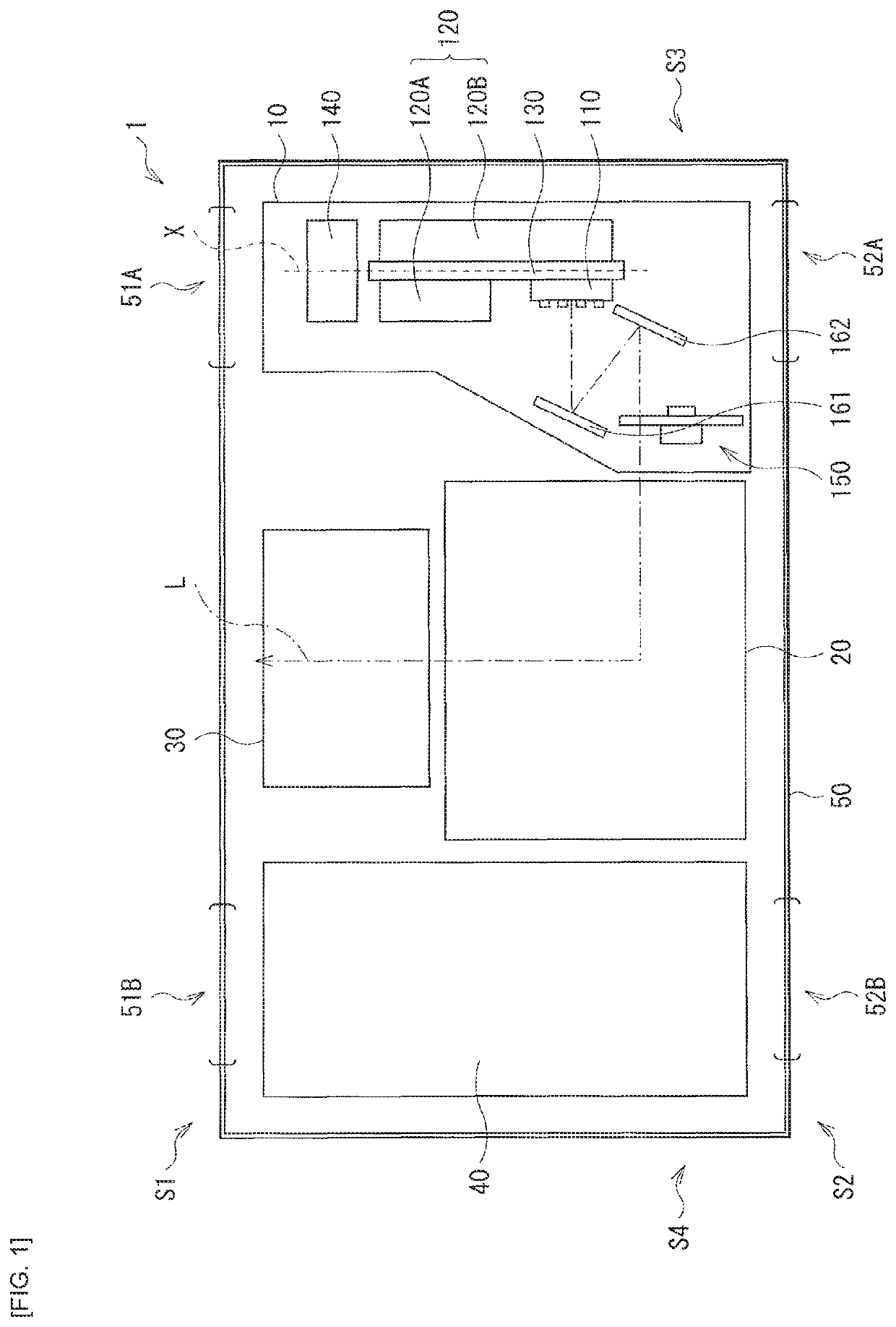
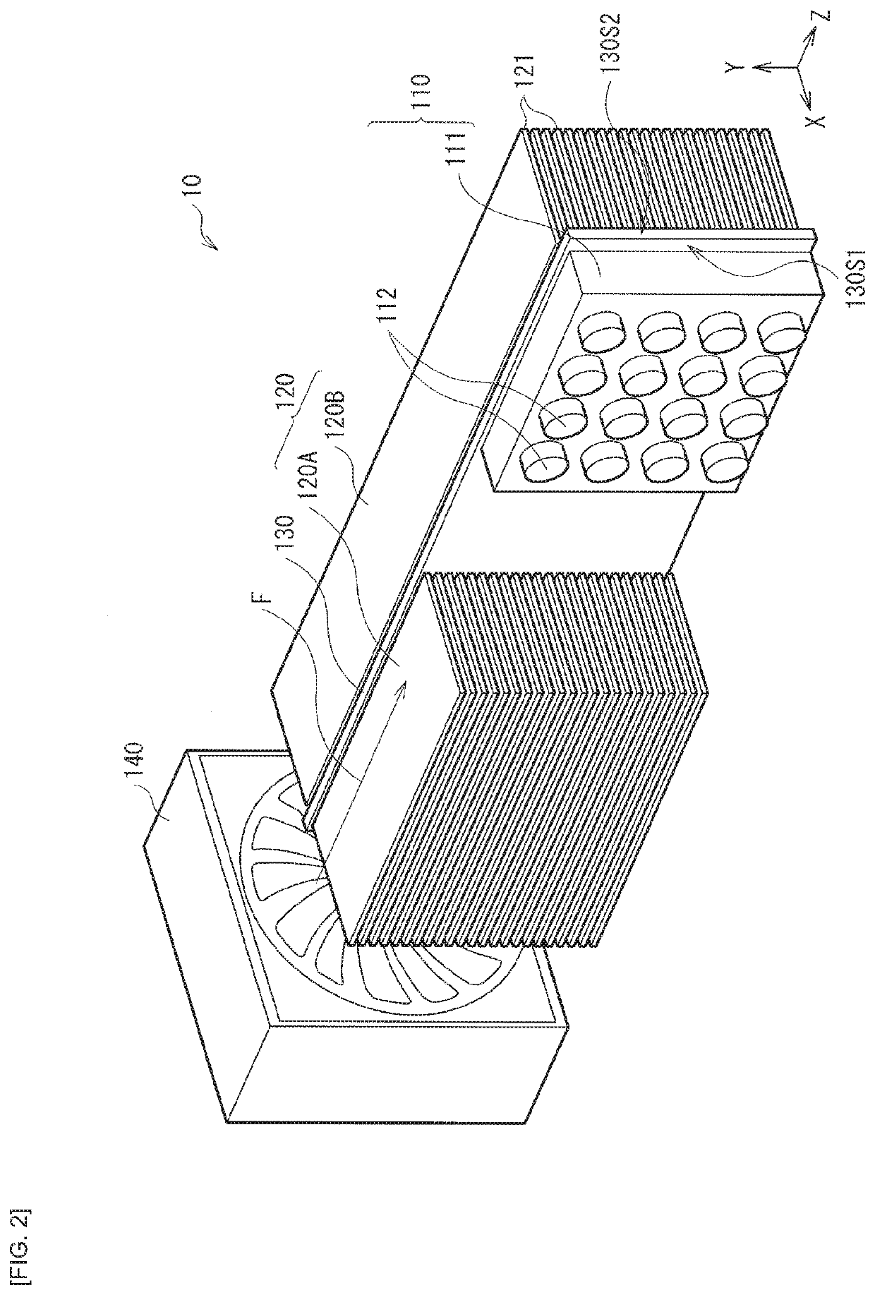
[0027]FIG. 1 illustrates an overall configuration of a projection display apparatus (projector 1) according to an embodiment of the present disclosure. The projector 1 is a projection display apparatus that projects an image (image light) on a screen (not illustrated) such as a wall surface, and includes a light source device 10, an image generation optical system 20, a projection optical system 30, a power supply unit 40, and a housing 50 that houses the light source device 10, the image generation optical system 20, the projection optical system 30, and the power supply unit 40. The light source device 10 includes, for example, a light source section 110, a light converter (phosphor wheel 150), and a cooler (cooling fan 140) that cools the light source section 110. In the present embodiment, the light source section 110 is mounted on a vapor chamber 130 together with a radiation fin 120. The light source device 10 has a configuration in which t...

modification example

2. Modification Example

[0063]Next, Modification Examples (Modification Examples 1 to 3) of the above-described embodiment are described. In the following, components similar to those of the above-described embodiment are denoted with the same reference numerals, and descriptions thereof are omitted where appropriate.

modification example 1

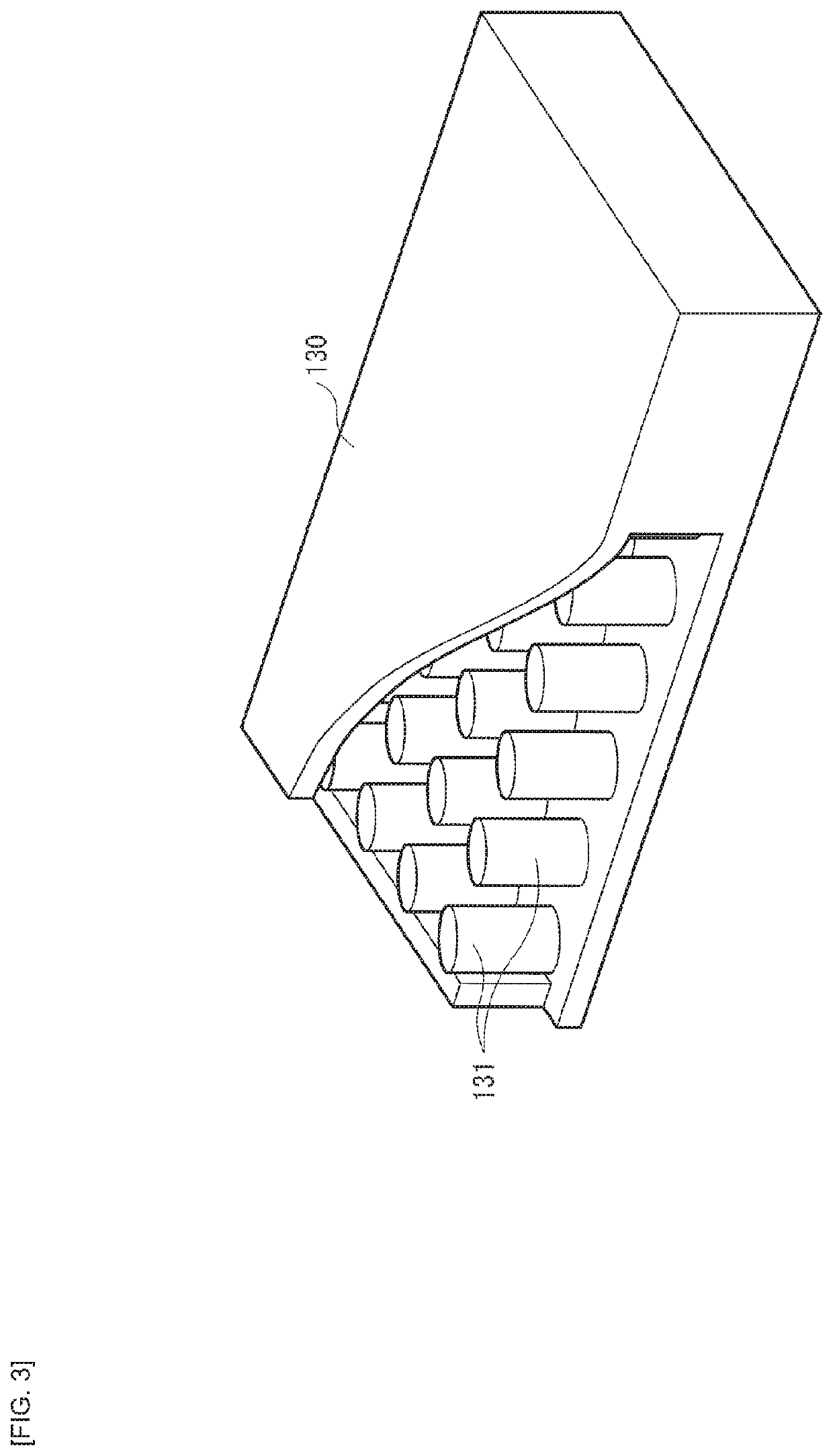
[0064]FIG. 7 illustrates a configuration of a main portion of a light source device (light source device 10A) included in a projection display apparatus (projector 1) according to Modification Example 1 of the present disclosure. Although the above-described embodiment presents an example in which the light source section 110 and the radiation fin 120A disposed on the surface 130S1 of the vapor chamber 130 are disposed in the order of the radiation fin 120A and then light source section 110 from side of the cooling fan 140, it is not limiting. For example, as illustrated in FIG. 7, the light source section 110 and the radiation fin 120A may be disposed in this order from side of the cooling fan 140.


PUM


Abstract

A projection display apparatus according to an embodiment of the present disclosure includes: a light source device; an image generation optical system that generates image light by modulating light from the light source device on the basis of an inputted image signal; and a projection optical system that projects the image light generated by the image generation optical system. The light source device includes a light source section, a radiation fin, a vapor chamber on which the light source section and the radiation fin are disposed, and a cooling fan. The light source section, the radiation fin, and the vapor chamber are disposed on a flow path of cooling gas sent out of the cooling fan.

Description

CROSS REFERENCE TO RELATED APPLICATIONS[0001]This application is a U.S. National Phase of International Patent Application No. PCT / JP2018 / 025033 filed on Jul. 2, 2018, which claims priority benefit of Japanese Patent Application No. JP 2017-156534 filed in the Japan Patent Office on Aug. 14, 2017. Each of the above-referenced applications is hereby incorporated herein by reference in its entirety.TECHNICAL FIELD[0002]The present disclosure relates to a projection display apparatus that uses a vapor chamber, for example, as a cooling member for a light source section.BACKGROUND ART[0003]Recently, various projectors have been developed, which projectors have a common problem that their set volume is large. One factor that increases the set volume is area occupied by a cooling device in the projector. Furthermore, a projector that uses a solid-state light source such as a semiconductor laser (laser diode; LD) as a light source is likely to have an increased volume of the light source s...

Claims


Application Information

Patent Timeline
IPC IPC(8): G03B21/16H04N9/31G02F1/1335G02B7/02G02F1/1333H05K7/20
CPCH04N9/3144G02B7/028G02F1/133385G02F1/133628G03B21/16H05K7/20972H04N9/3158
Inventor USAMI, KAZUMA
Owner SONY CORP
Features
  • Generate Ideas
  • Intellectual Property
  • Life Sciences
  • Materials
  • Tech Scout
  • Unparalleled Data Quality
  • Higher Quality Content
  • 60% Fewer Hallucinations
Learn More