Actuator device

a technology of actuators and actuators, applied in piezoelectric/electrostrictive/magnetostrictive devices, microelectromechanical systems, instruments, etc., can solve problems such as deterioration in controllability and characteristic, and achieve the effects of suppressing metal fatigue, improving reliability, and reducing the resistance of wiring

Active Publication Date: 2021-12-14
HAMAMATSU PHOTONICS KK
View PDF16 Cites 7 Cited by
  • Summary
  • Abstract
  • Description
  • Claims
  • Application Information

AI Technical Summary

Benefits of technology

[0021]According to an aspect of the invention, it is possible to provide an actuator device capable of improving reliability while decreasing a resistance of a wiring provided on a connection portion and suppressing a metal fatigue thereof.

Problems solved by technology

For that reason, when metal such as aluminum or copper is used as a wiring material, there is a possibility of deterioration in controllability due to hysteresis behavior, work hardening, or the like, a change in characteristic with time, and the like.
As a result, deterioration in characteristic, a disconnection, or the like occurs.

Method used


Image

  • Actuator device
  • Actuator device
  • Actuator device

Examples


Embodiment Construction

[0033]Hereinafter, an embodiment according to an aspect of the invention will be described in detail with reference to the drawings. Additionally, in the description below, the same reference numerals will be given to the same or equivalent components and a redundant description thereof will be omitted.

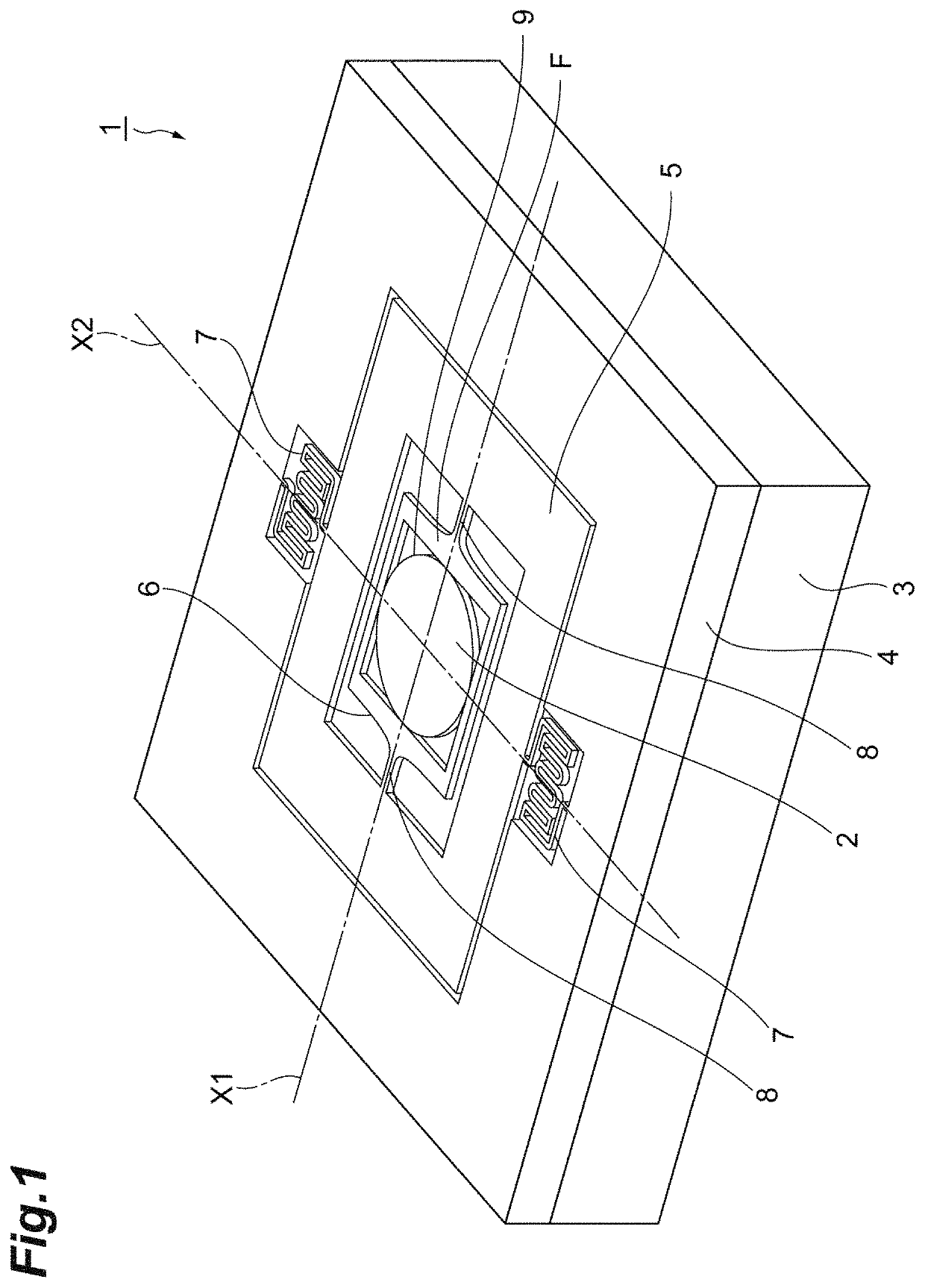
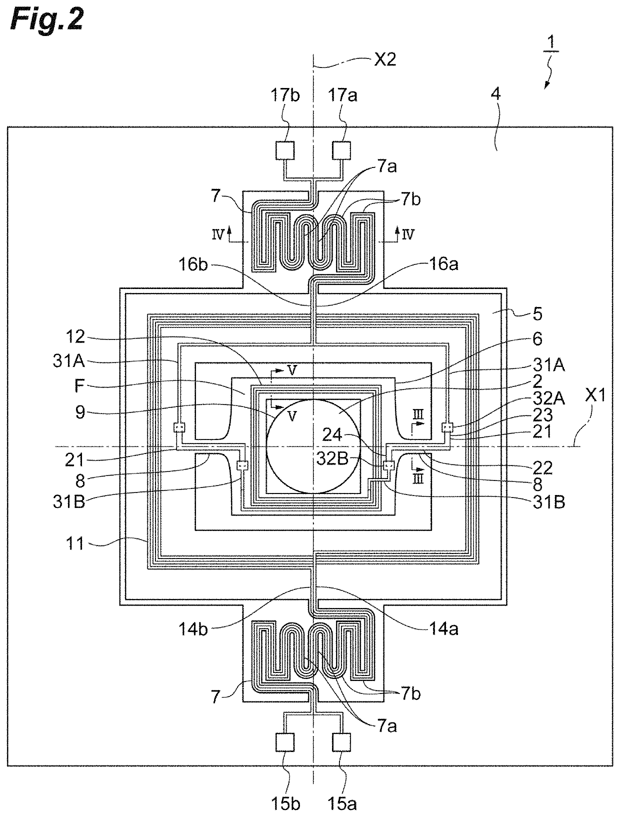
[0034]As illustrated in FIGS. 1 and 2, an actuator device 1 includes a mirror 2, a magnetic field generator 3, a frame portion 4, a support portion 5, a movable portion 6, a pair of second connection portions 7, and a pair of first connection portions 8. The actuator device 1 is configured as an MEMS device that swings the mirror 2 around each of a first axis X1 and a second axis X2 which are orthogonal to each other. Such an actuator device 1 is used in, for example, an optical communication switch or an optical scanner.

[0035]The mirror 2 is a light reflecting film which is formed by a metal film. The mirror 2 has a circular shape in plan view (when viewed from a direction orthogonal...


PUM


Abstract

An actuator device includes: a support portion; a movable portion; a first connection portion connecting the movable portion to the support portion on a first axis so that the movable portion is swingable around the first axis; and a first wiring provided on the first connection portion. The first wiring includes a first main body formed of a metal material having a Vickers hardness of 50 HV or more. The first main body includes a first surface facing the first connection portion and a second surface other than the first surface. The second surface has a shape in which a curvature is continuous over the entire second surface in a cross-section perpendicular to an extension direction of the first wiring.

Description

TECHNICAL FIELD[0001]An aspect of the invention relates to an actuator device configured as, for example, a micro electro mechanical systems (MEMS) device.BACKGROUND ART[0002]As an MEMS device, there is known an actuator device including a support portion, a movable portion, a connection portion connecting the movable portion to the support portion on an axis so that the movable portion is swingable around a predetermined axis, and a wiring provided on the connection portion. In such an actuator device, for example, the movable portion may swing at a high speed of a resonance frequency level (several kHz to several tens of kHz). For that reason, when metal such as aluminum or copper is used as a wiring material, there is a possibility of deterioration in controllability due to hysteresis behavior, work hardening, or the like, a change in characteristic with time, and the like. As a result, deterioration in characteristic, a disconnection, or the like occurs.[0003]In order to solve t...

Claims


Application Information

Patent Timeline
Patent Type & Authority Patents(United States)
IPC IPC(8): G02B26/08B81B3/00G02B26/10
CPCG02B26/085B81B3/0075G02B26/10B81B2201/042B81B7/02B81B7/0009B81B2201/03B81B3/00G02B26/105B81B3/0008
Inventor SUZUKI, DAIKIMORINAGA, YUKITANAKA, GO
Owner HAMAMATSU PHOTONICS KK
Why Eureka
Try Eureka