Cascaded fuel cell stack and fuel cell system

a fuel cell and cascade technology, applied in the field of cascaded fuel cell stack and fuel cell system, can solve the problems of operational instabilities and water accumulation risk, and achieve the effect of optimizing water management and stable operation

Active Publication Date: 2021-12-14
AUDI AG
View PDF25 Cites 0 Cited by
  • Summary
  • Abstract
  • Description
  • Claims
  • Application Information

AI Technical Summary

Benefits of technology

[0003]Described herein is a fuel cell stack of the type mentioned initially and a fuel cell system in such a way that stable operation with optimized water management is achieved.
[0004]As described herein, the membrane electrode assemblies and / or the gas diffusion layers within the second fuel cell segment are designed to be more water-repellent than those of the first fuel cell segment. This means that the components of the second fuel cell segment thus have a hydrophobic effect that is more pronounced than is the case with the components of the first fuel cell segment. The first fuel cell segment is therefore designed for dry inlet conditions and a small amount of water, while the second fuel cell segment is designed for high gas humidity and a large amount of water.
[0009]In another advantageous embodiment, the thickness of the membranes of the first fuel cell segment is less than the thickness of the membranes of the second fuel cell segment. In a further advantageous embodiment, the thickness of the membranes of the first fuel cell segment is between 4 micrometers (μm) and 12 micrometers and the thickness of the membranes of the second fuel cell segment is between 14 micrometers and 35 micrometers. In dry application conditions, the water balance can be improved by the thinner membrane; in this case, water transport is facilitated.
[0010]Another alternative embodiment is characterized in that the gas diffusion layers of the second fuel cell segment have a greater porosity than those of the first fuel cell segment. The greater porosity facilitates the discharge of water from the fuel cell stack, in particular from the second fuel cell segment, and thus where a higher humidity occurs. For example, the average pore size of the gas diffusion layers of the first fuel cell segment is less than 5 micrometers, preferably even less than 1 micrometer. The average pore size of the second fuel cell segment is then greater than 5 micrometers, for example, 10 micrometers. Water absorption and flooding possibly resulting therefrom within the second fuel cell segment can thus be prevented. Alternatively or additionally, the thickness of the gas diffusion layers of the first fuel cell segment may be less than the thickness of the gas diffusion layers of the second fuel cell segment.
[0013]Alternatively or additionally, the fuel cells may comprise one or more bipolar plates having a flow field for providing reaction media. In this case, the bipolar plates of the first fuel cell segment may be provided with a hydrophilic coating that makes them more water-attracting. Alternatively or additionally, the bipolar plates of the second fuel cell segment may be provided with a hydrophobic coating that makes them more water-repellent.

Problems solved by technology

There is the risk of water accumulation in the second fuel cell segment, which is located downstream.
This water accumulation leads to operational instabilities.

Method used


Image

  • Cascaded fuel cell stack and fuel cell system
  • Cascaded fuel cell stack and fuel cell system

Examples


Embodiment Construction

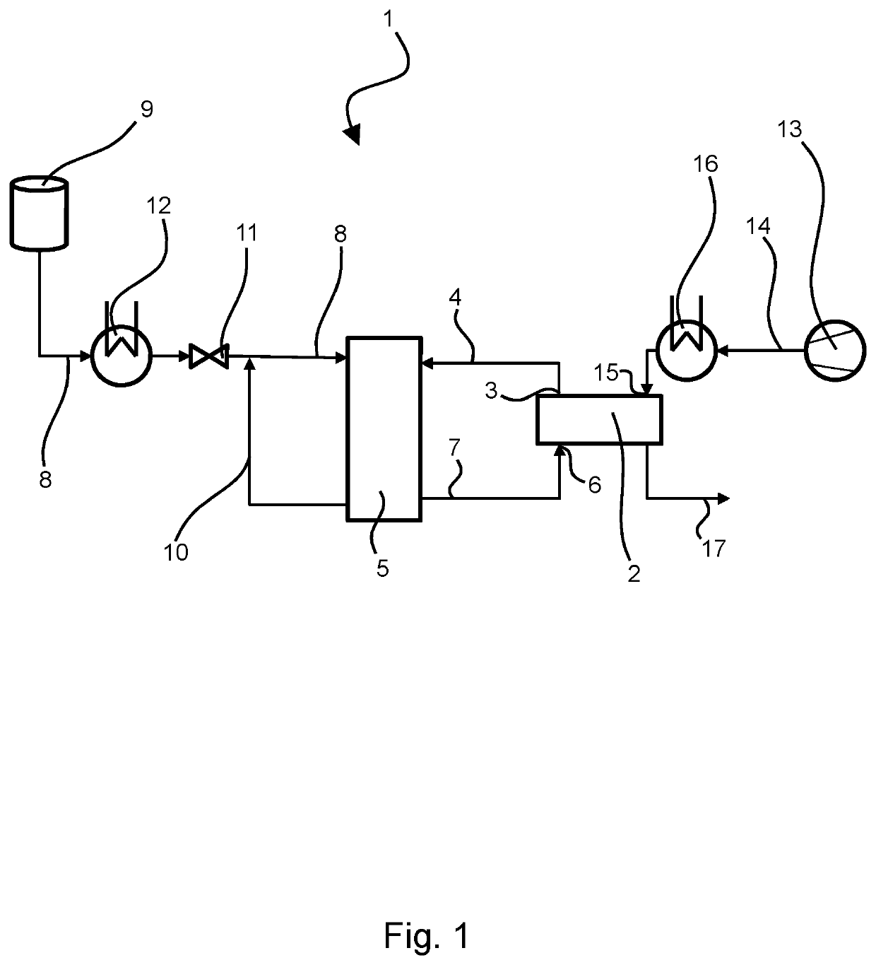
[0019]FIG. 1 shows a fuel cell system 1 which has a humidifier 2 on the cathode side. With its cathode-side outlet 3, the humidifier 2 is connected via a cathode supply line 4 to cathode spaces of a cascaded fuel cell stack 5. In addition, the humidifier 2 is connected with its cathode-side inlet 6 to the cathode spaces via a cathode exhaust gas line 7 through which unreacted cathode gas or moist cathode exhaust gas is returned to the humidifier 2. The cathode gas (e.g., air or oxygen) can be routed through the cathode spaces to the cathodes 30 of the plurality of fuel cells 18 arranged in the cascaded fuel cell stack 5. The cathode gas is drawn in by means of a compressor 13 and then introduced into a supply line 14. In the example shown, the incoming compressed cathode gas is cooled by means of a (recuperative) heat exchanger 16 before being fed into a cathode gas inlet 15 of the humidifier 2 for humidification. The humidifier 2 is composed of a plurality of water-vapor-permeable ...


PUM

PropertyMeasurementUnit
thicknessaaaaaaaaaa
thicknessaaaaaaaaaa
thicknessaaaaaaaaaa

Abstract

A fuel cell stack is provided comprising a plurality of fuel cells comprising a membrane electrode assembly and at least one gas diffusion layer, which fuel cells are divided into at least one first fuel cell segment having a portion of the plurality of fuel cells and a second fuel cell segment having a different portion of the plurality of fuel cells, wherein the first fuel cell segment and the second fuel cell segment are arranged in a common fuel cell cascade, wherein the first fuel cell segment comprises a first collector inlet line for an operating medium and a first collector outlet lined which is formed integrally with a second collector inlet line of the second fuel cell segment and wherein the second fuel cell segment comprises a second collector outlet line. The membrane electrode assemblies and / or the gas diffusion layers inside the second fuel cell segment are designed in such a way that they are more water-repellent than those of the first fuel cell segment. A fuel cell system comprising such a fuel cell stack is also provided.

Description

BACKGROUNDTechnical Field[0001]Described herein is a fuel cell stack having a plurality of fuel cells comprising a membrane electrode assembly and at least one gas diffusion layer. At least two gas diffusion layers are preferably provided in each case. The fuel cells are divided into at least a first fuel cell segment having a portion of the plurality of fuel cells and a second fuel cell segment having a different or further portion of the plurality of fuel cells. The first fuel cell segment and the second fuel cell segment are arranged in a common fuel cell cascade. The first fuel cell segment comprises a first collector inlet line for an operating medium and a first collector outlet line formed integrally with a second collector inlet line of the second fuel cell segment. The second fuel cell segment also includes a second collector outlet line. Further described herein is a corresponding fuel cell system, such as for use in a motor vehicle, with such a fuel cell stack. The first ...

Claims


Application Information

Patent Timeline
Patent Type & Authority Patents(United States)
IPC IPC(8): H01M8/241H01M8/1004H01M8/249H01M8/1007H01M8/04291H01M8/1067H01M8/2457H01M8/04119H01M8/1018
CPCH01M8/241H01M8/04291H01M8/1004H01M8/1007H01M8/1067H01M8/249H01M8/2457H01M8/04149H01M2008/1095H01M2250/20H01M4/8657H01M8/0228H01M8/04119Y02E60/50H01M8/0245
Inventor ERMATSCHENKO, NATALJALUCAS, CHRISTIANHÜBNER, GEROLD
Owner AUDI AG
Why Eureka
Try Eureka