Method and charging device for determining a maximum storage capacity of an energy store

a technology for energy stores and maximum storage capacity, applied in secondary cell servicing/maintenance, battery/fuel cell control arrangements, instruments, etc., can solve the problems of high cost and inability to accurately and accurately determine the capacity, and achieve the effect of easy and reliable determination of the maximum storage capacity of an energy stor

Active Publication Date: 2021-12-28
DR ING H C F PORSCHE AG
View PDF7 Cites 0 Cited by
  • Summary
  • Abstract
  • Description
  • Claims
  • Application Information

AI Technical Summary

Benefits of technology

[0014]On the basis of the above-mentioned prior art, described herein is a method and a charging device of the above-mentioned type which make it possible to easily and reliably determine a maximum storage capacity of an energy store, in particular as a drive battery of a vehicle with an electrical drive, of the above-mentioned type.
[0017]According to one aspect, described is a method of calculating the maximum capacity of an energy store by completely discharging the completely charged energy store, wherein charge from the energy store can be buffered by the energy storage unit. With complete discharging of the energy store, the maximum capacity of the energy store can be determined in a particularly reliable manner in comparison with other methods which only estimate the maximum capacity of the energy store on the basis of charging and / or discharging characteristics. In this case, the method can also be carried out in a particularly cost-effective manner since, on account of the energy storage unit, the electrical charge from the energy store generally does not have to be discharged or converted in another manner, but rather buffering can be carried out. In addition, both the charging and the discharging can be carried out in a particularly short time since the energy storage unit can be used as a booster both for the charging and for the discharging of the energy store if only a small network connection (that is to say with a low charging power) is available, for example.
[0024]In an advantageous configuration of the invention, the method comprises an additional step for discharging the separate energy storage unit, in particular for charging the energy store. As a result, charge stored in the energy storage unit can be used to charge the energy store, with the result that the latter can be completely charged. Ideally, it is possible to completely dispense with feeding electrical energy stored in the energy storage unit back into the connected energy network. In addition, as a result of the previous discharging of the energy storage unit, the energy store can be completely or largely discharged into the energy storage unit. The method can therefore be carried out in a particularly cost-effective manner. The separate energy storage unit can be discharged at the same time as the charging of the energy store if the energy from the energy storage unit is transferred to the energy store while the latter is completely charged.
[0025]In an advantageous configuration of the invention, the charging and / or the complete discharging of the energy store using a separate energy storage unit for receiving / delivering the charge of the energy store comprise(s) charging / discharging the energy store according to a defined charging / discharging profile. This makes it possible to ensure that the energy store is reliably charged / discharged and its maximum capacity can be correctly determined. Damage to the energy store during charging / discharging can be avoided. At the same time, the method can be carried out efficiently since unnecessary time losses as a result of uncontrolled discharging of the energy store are prevented.
[0034]In a further configuration of the invention, it is possible to carry out the renewed charging of the energy store from the energy storage unit until it reaches its maximum amount of charge.

Problems solved by technology

However, this is very complicated and is associated with high costs.
However, it is not possible to completely and accurately determine the capacity.

Method used


Image

  • Method and charging device for determining a maximum storage capacity of an energy store
  • Method and charging device for determining a maximum storage capacity of an energy store

Examples


Embodiment Construction

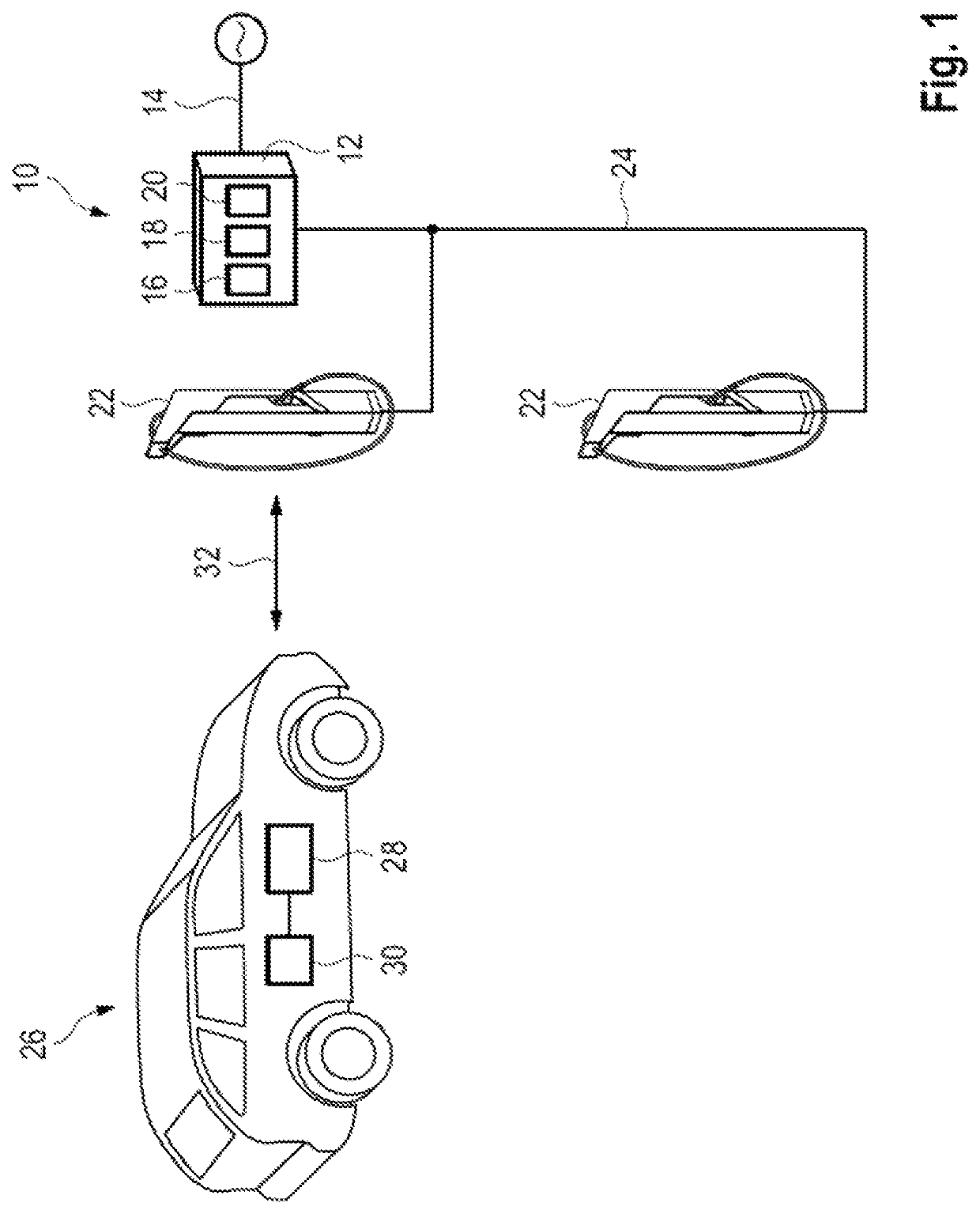
[0040]FIG. 1 shows a charging device 10 according to the invention in accordance with a first preferred embodiment. The charging device 10 is designed for fast-charging with DC voltage and direct current.

[0041]In this exemplary embodiment, the charging device 10 comprises a charge box 12 which is connected to an energy network 14. The charge box 12 is designed to take electrical energy from the energy network 14 and to deliver electrical energy to the energy network 14. The energy network 14 is typically designed with AC voltage and alternating current.

[0042]In this exemplary embodiment, the charge box 12 comprises a cooling unit 16, power electronics 18 and an energy storage unit 20. The cooling unit 16 is used to control the temperature of the power electronics 18 and / or of the energy storage unit 20. The power electronics 18 convert electrical energy from the energy network 14 into a DC voltage / direct current. The power electronics 18 can also carry out a conversion in the opposi...


PUM

PropertyMeasurementUnit
chargeaaaaaaaaaa
energyaaaaaaaaaa
temperatureaaaaaaaaaa

Abstract

A method for determining a maximum storage capacity of an energy store, in particular as a drive battery of a vehicle with an electrical drive, including the steps of determining a state of charge of the energy store of the vehicle, charging the energy store until it reaches its maximum amount of charge, completely discharging the energy store using a separate energy storage unit for receiving the charge of the energy store, wherein an amount of charge transferred from the energy store to the energy storage unit is captured, and outputting the transferred amount of charge upon complete discharging of the energy store as the maximum capacity of the energy store.

Description

CROSS-REFERENCE TO RELATED APPLICATION[0001]This application claims priority to German Patent Application No. 10 2019 106 240.3, filed Mar. 12, 2019, the content of such application being incorporated by reference herein in its entirety.FIELD OF THE INVENTION[0002]The present invention relates to a method for determining a maximum storage capacity of an energy store, in particular as a drive battery of a vehicle with an electrical drive.BACKGROUND OF THE INVENTION[0003]The invention also relates to a charging device for the fast-charging of an energy store, in particular as a drive battery of a vehicle with an electrical drive, comprising a charging pole, and a charge box which is connected between an energy network and the charging pole and provides the charging pole with electrical energy for fast-charging with high DC voltages and direct currents, wherein the charge box can have an energy storage unit, and the charging device is configured to carry out the above method.[0004]The ...

Claims


Application Information

Patent Timeline
Patent Type & Authority Patents(United States)
IPC IPC(8): H02J7/00B60L53/62G01R31/385G01R31/392G01R31/374B60L50/60B60L58/12B60L53/31G01R31/382B60L55/00H01M10/44H02J7/34B60L53/18
CPCB60L53/62B60L50/66B60L53/31B60L55/00B60L58/12G01R31/374G01R31/382G01R31/385G01R31/392H01M10/44H02J7/0048H02J7/342B60L53/18Y02T90/12B60L53/53B60L58/10B60L58/16Y02T10/70Y02T10/7072Y02E60/10Y02T90/14
Inventor HEYNE, RAOULVOLK, DOMINIK
Owner DR ING H C F PORSCHE AG
Why Eureka
Try Eureka