Magnetic marker installation method

a magnetic marker and installation method technology, applied in the field of magnetic marker installation methods, can solve the problems of insufficient amount and types of information that can be acquired from the side of the magnetic marker, and achieve the effects of reducing the possibility of impairing the reliability of wireless communication, reducing the possibility of impairing the stability of wireless communication, and increasing the number of information

Active Publication Date: 2022-02-01
AICHI STEEL
View PDF15 Cites 0 Cited by
  • Summary
  • Abstract
  • Description
  • Claims
  • Application Information

AI Technical Summary

Benefits of technology

[0009]With the magnetic marker including the wireless tag, more information can be provided to a vehicle side by using wireless communication. On the other hand, in the event of rain or the like in which there is a possibility that a periphery of the magnetic marker is submerged in water, stability of wireless communication may be impaired due to influences of water exhibiting electromagnetic characteristics which attenuate electric waves.
[0010]To address this, the magnetic marker installation method of the present invention includes the formation step of providing the protecting part which isolates the antenna from water. By installing the magnetic marker with the installation method including the formation step of providing the protecting part, even if water is present on the periphery of the magnetic marker in the event of rain, for example, it is possible to reduce a possibility of impairing reliability of wireless communication.
[0011]As described above, according to the magnetic marker installation method of the present invention, the magnetic marker can be installed so that more information can be stably provided to the vehicle side.

Problems solved by technology

However, there is a problem that information that can be acquired by detecting a magnetic marker includes information about presence or absence of the magnetic marker, a shift amount in a width direction of a vehicle with respect to the magnetic marker, whether magnetic polarity indicates the N pole or the S pole, and so forth, and the amount and types of information that can be acquired from a magnetic marker side are not sufficient.

Method used


Image

  • Magnetic marker installation method
  • Magnetic marker installation method
  • Magnetic marker installation method

Examples


first embodiment

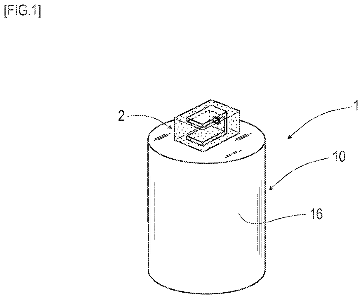
[0034]The present embodiment is an example of a method of installing magnetic marker 1 including RFID tag (Radio Frequency IDentification Tag, wireless tag) 2. Details of this are described by using FIG. 1 to FIG. 12.

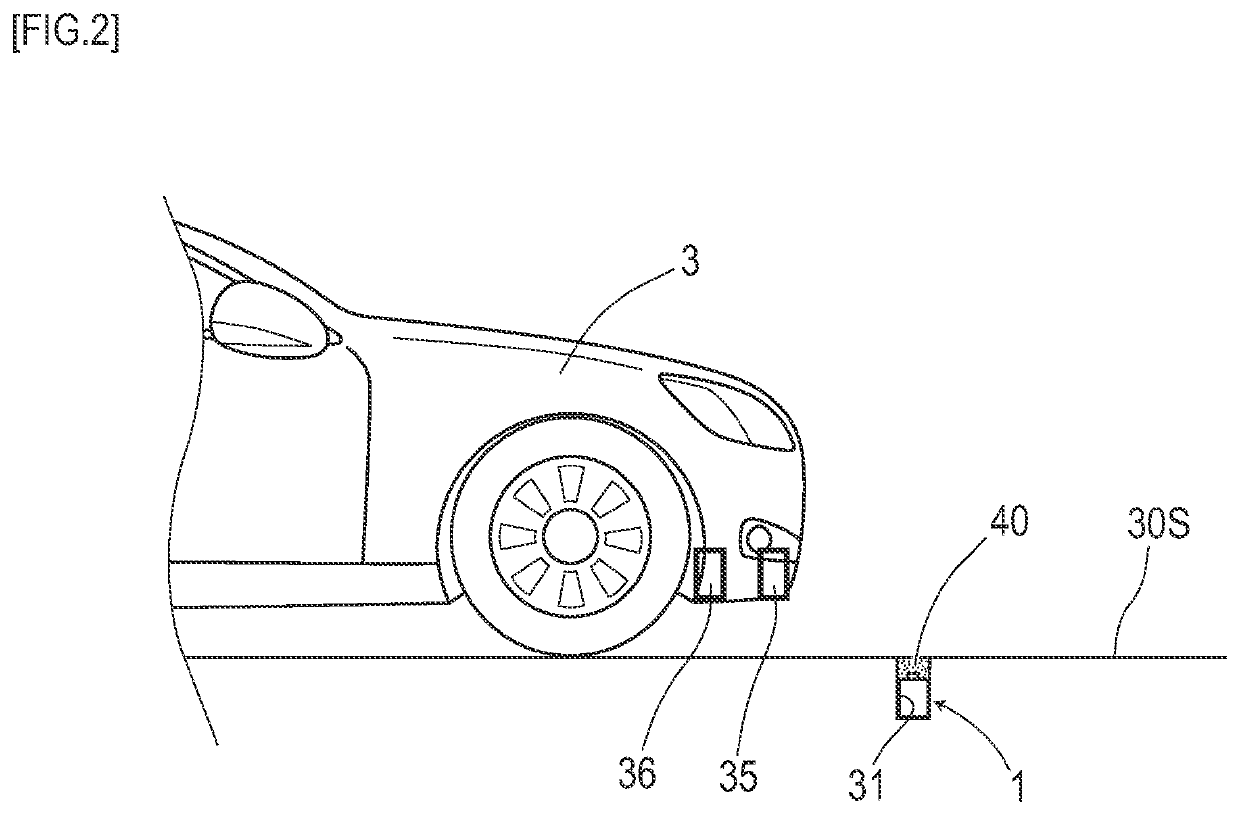
[0035]Magnetic marker 1 to be installed is, as in FIG. 1 and FIG. 2, a road marker arranged in road surface 30S, for example, along a center of a lane, for use in various vehicle controls, such as lane departure warning, a lane keep assist, and automatic driving. In this magnetic marker 1, RFID tag 2 which provides information by wireless communication is retained on one end face of columnar magnet 10.

[0036]With vehicle 3 (FIG. 2) equipped with magnetic sensor unit 35 which detects magnetism and tag reader unit 36 communicable with RFID tag 2, magnetic marker 1 can be magnetically detected during travel, and tag information can be acquired via wireless communication with RFID tag 2. Examples of the tag information include information indicating an absolute position, ide...

second embodiment

[0085]The present embodiment is an example of a method of installing magnetic marker 1 based on the magnetic marker of FIG. 12 exemplarily depicted as a modification example in the first embodiment, with a change of the arrangement location of RFID tag 20 from the end face to the outer peripheral side surface of the magnet. Details of this are described with reference to FIG. 13 to FIG. 18.

[0086]In magnetic marker 1 of the present embodiment, as in FIG. 13, metal foil 25 provided with slit-shaped gap 250 is arranged so as to be wound around the outer peripheral side surface of magnet 10 and sheet-shaped RFID tag 20 is arranged in that slit-shaped gap 250. Metal foil 25 is formed of a laterally-elongated, substantially-rectangular shape, as in a development view of FIG. 14, with the lateral-width dimension being shorter than the periphery length of magnet 10. Therefore, when this metal foil 25 is formed so as to be wound around magnet 10, the length of the metal foil is insufficient ...

third embodiment

[0097]The present embodiment is an example based on the first embodiment, with a change to a sheet-shaped magnetic marker 1. Details of this are described by using FIG. 19 to FIG. 21.

[0098]Magnetic marker 1 of the present embodiment retains sheet-shaped RFID tag 27 on a surface of magnet sheet 10, as in FIG. 19.

[0099]Magnetic marker 1 is a marker that is formed of a flat circular shape having a diameter of 100 mm and a thickness of 1.5 mm and can be adhesively bonded to a road surface. Magnet sheet 10 forming this magnetic marker 1 is made by forming an isotropic ferrite rubber magnet having a maximum energy product (BH max)=6.4 kJ / m3 into a sheet shape.

[0100]As in FIG. 20, by adopting antenna 272 of a pattern being wound in a spiral shape, RFID tag 27 has its antenna performance enhanced. RFID tag 27 is formed of a sheet shape with a size of 3 mm×4 mm. This RFID tag 27 does not require an external antenna, and can singly communicate with a vehicle side. In RFID tag 27, gap 270 of s...


PUM


Abstract

To install, in or on a road surface of a road, a magnetic marker having retained in its outer perimeter an RFID tag including an antenna for wireless communication, an arrangement step of accommodating the magnetic marker in an accommodation hole provided to be bored in the road surface and a formation step of providing the magnetic marker with a protecting part for isolating the antenna from water are performed. With these steps, even if the periphery of the magnetic marker is submerged in water after installation, high communication performance of the RFID tag can be kept.

Description

TECHNICAL FIELD[0001]The present invention relates to a method of installing a magnetic marker to be laid in or on a road.BACKGROUND ART[0002]Conventionally, magnetic markers to be laid in a road so as to be detectable by a vehicle side have been known (for example, refer to Patent Literature 1). If the magnetic markers are utilized, there is a possibility of achieving automatic driving as well as various driving assists such as, for example, automatic steering control and lane departure warning by using the magnetic markers laid along a lane.[0003]However, there is a problem that information that can be acquired by detecting a magnetic marker includes information about presence or absence of the magnetic marker, a shift amount in a width direction of a vehicle with respect to the magnetic marker, whether magnetic polarity indicates the N pole or the S pole, and so forth, and the amount and types of information that can be acquired from a magnetic marker side are not sufficient. Thu...

Claims


Application Information

Patent Timeline
Patent Type & Authority Patents(United States)
IPC IPC(8): E01F11/00G08G1/042
CPCE01F11/00G08G1/042E01F9/30
Inventor YAMAMOTO, MICHIHARUNAGAO, TOMOHIKOAOYAMA, HITOSHI
Owner AICHI STEEL
Why Eureka
Try Eureka