Spark chamber for optical emission analysis

a spark chamber and optical emission technology, applied in the field of improved spark chambers for optical emission spectrometers, can solve the problems of inability to accurately measure, inability to accurately record nitrogen signals, and high cost of argon and other inert gases, and achieves rapid drop in flow velocity, increase in unobstructed cross sectional area, and high gas flow velocity

Active Publication Date: 2015-09-08
THERMO FISHER SCI ECUBLENS
View PDF15 Cites 0 Cited by
  • Summary
  • Abstract
  • Description
  • Claims
  • Application Information

AI Technical Summary

Benefits of technology

[0022]Preferably the spark chamber internal shape and components placed within the spark chamber are such that turbulence is substantially eliminated, as will be further described.
[0025]It has been found by the present inventors that the geometry of the internal volume of the spark chamber strongly influences the efficiency with which particulate and vaporised materials are swept from the chamber volume. Typical prior art spark chambers possess gas inlet tubes which are of a relatively small diameter compared to the maximum unobstructed internal diameter of the spark chamber. A small diameter gas inlet has often been favoured in order to ensure that there is a high gas flow velocity through the inlet tube so as to prevent backstreaming of materials onto the collection optics of the analyser, which, as noted above, lie upstream of the spark chamber. The relatively small gas inlet tube terminates at the spark chamber abruptly. Examples of such prior art systems are found in U.S. Pat. Nos. 5,699,155, 4,289,402 and CN1796983A. In these prior art systems, the unobstructed internal cross sectional area of the spark chamber perpendicular to the flow axis increases rapidly from the gas inlet as the gas travels into the chamber, as the chamber is cylindrical in shape with the gas inlet terminating on one curved side of the cylinder. Typically the ratio of the maximum unobstructed internal cross sectional area of the spark chamber perpendicular to the flow axis to its minimum at the gas inlet is 2.5. There is an abrupt change in the resistance to flow of the gas immediately after passing into the spark chamber from the gas inlet and, due to the increase in unobstructed cross sectional area, the flow velocity drops rapidly. These effects frequently result in turbulence, eddying, generally rotational or re-circulating flow patterns, and stagnation. Such gas flow conditions promote the re-deposition of material within the spark chamber, especially onto the chamber walls, with the possibility of material back-streaming along the gas inlet tube and being deposited onto the light collection optics. Low gas flow rates together with recirculation can result in the residence time of metal vapours from the discharge process being sufficiently long such that condensation occurs upon exposed surfaces such as the chamber walls and the insulator. Material deposition on the surfaces of the optics, the insulator or the chamber walls results in an increase in instrument down time for maintenance. Furthermore, turbulent flow impairs the stability of the electrical discharge, which can result in reduced precision of measurement.
[0026]The inventors realised that in contrast to the gas flow conditions promoted by prior art spark chamber geometries, a laminar gas flow is highly desirable to counter these effects and, that to produce such a laminar gas flow, the unobstructed internal cross sectional area of the spark chamber should be relatively constant along the gas flow axis which passes from the gas inlet to the gas outlet. The gas inlet and gas outlet should terminate at the spark chamber with relatively large cross sectional areas so that the gas flow rate does not change abruptly in these regions. Multiple gas inlet and gas orifices could be used to provide this characteristic, but preferably a single gas inlet orifice and a single gas outlet orifice is utilised. A single gas inlet orifice has the additional advantage that light from the discharge process may be efficiently transmitted along the gas inlet to the light collection optics of the spectrometer, especially so with a single gas inlet orifice having relatively large cross sectional area. Multiple inlet and / or outlet orifices may also promote areas in which turbulence and recirculation can occur, local to the inlet or outlet.
[0027]Utilisation of a spark chamber in which the unobstructed internal cross sectional area perpendicular to the gas flow axis remains relatively constant from the gas inlet to the gas outlet enables the present invention purge the spark chamber at significantly reduced rates of gas flow, yet with improved debris clearance characteristics. Typical prior art spark chambers utilise a 5 l / min gas flow rate; the present invention has allowed a 3 l / min gas flow rate to be used yet with superior purging characteristics. Lower gas flow rates result in lower running costs. The present invention may utilise any inert gas, as known in the art, preferably argon. The laminar flow characteristics provide less turbulence, less recirculation and hence less deposition and better debris clearance, resulting in less down time for cleaning the spark chamber, typically between two and three times lower. The laminar flow also promotes a more stable electrical discharge resulting in a higher level of reproducibility, leading to improved precision of analysis. As noted above, for analysis of the nitrogen content of a sample, outgassing of residual nitrogen from material at the internal surfaces of the walls of the spark chamber has been found to cause instability of the recorded nitrogen signal, and inaccuracy of the measured result, with high background nitrogen signal measured immediately after insertion of a sample. Appropriate choice of the inner wall chamber materials provided with a fine surface finish, suppression of dead or stagnant volumes plus a well designed argon flow pattern to efficiently rinse the chamber as provided by the present invention all promote outgassing of the residual nitrogen down to a level which allows to reach the necessary sensitivity and stability from the first run.

Problems solved by technology

For analysis of the nitrogen content of a sample, outgassing of residual nitrogen from material at the internal surfaces of the walls of the spark chamber has been found to cause instability of the recorded nitrogen signal, and inaccuracy of the measured result with a high background nitrogen signal recorded after insertion of a new sample.
Several sequences of electrical discharges must be made on a sample before this residual nitrogen reduces sufficiently and this is undesirable for high throughput instruments in which precise and reliable nitrogen analysis is desired from the first run.
However, argon and other inert gases are expensive and contribute to the running costs of the spectrometer and it is desirable that the lowest possible flow of inert gas is used which will be adequate for the purposes described above.
However this prior art method suffers from poor evacuation of debris from the spark chamber.
This arrangement suffers from the disadvantage that the cyclone-type gas flow generated carries particulate material towards the chamber walls, where it accumulates, rather than sweeping it from the chamber.
The symmetrical disposition of the gas inlets promotes a more stable electrical discharge, but again evacuation of debris is not efficiently accomplished.
However this method may promote after-pulsing of residual gas flow which could carry particulate debris towards the collection optics, and thereby contaminate them.

Method used


Image

  • Spark chamber for optical emission analysis
  • Spark chamber for optical emission analysis
  • Spark chamber for optical emission analysis

Examples


Embodiment Construction

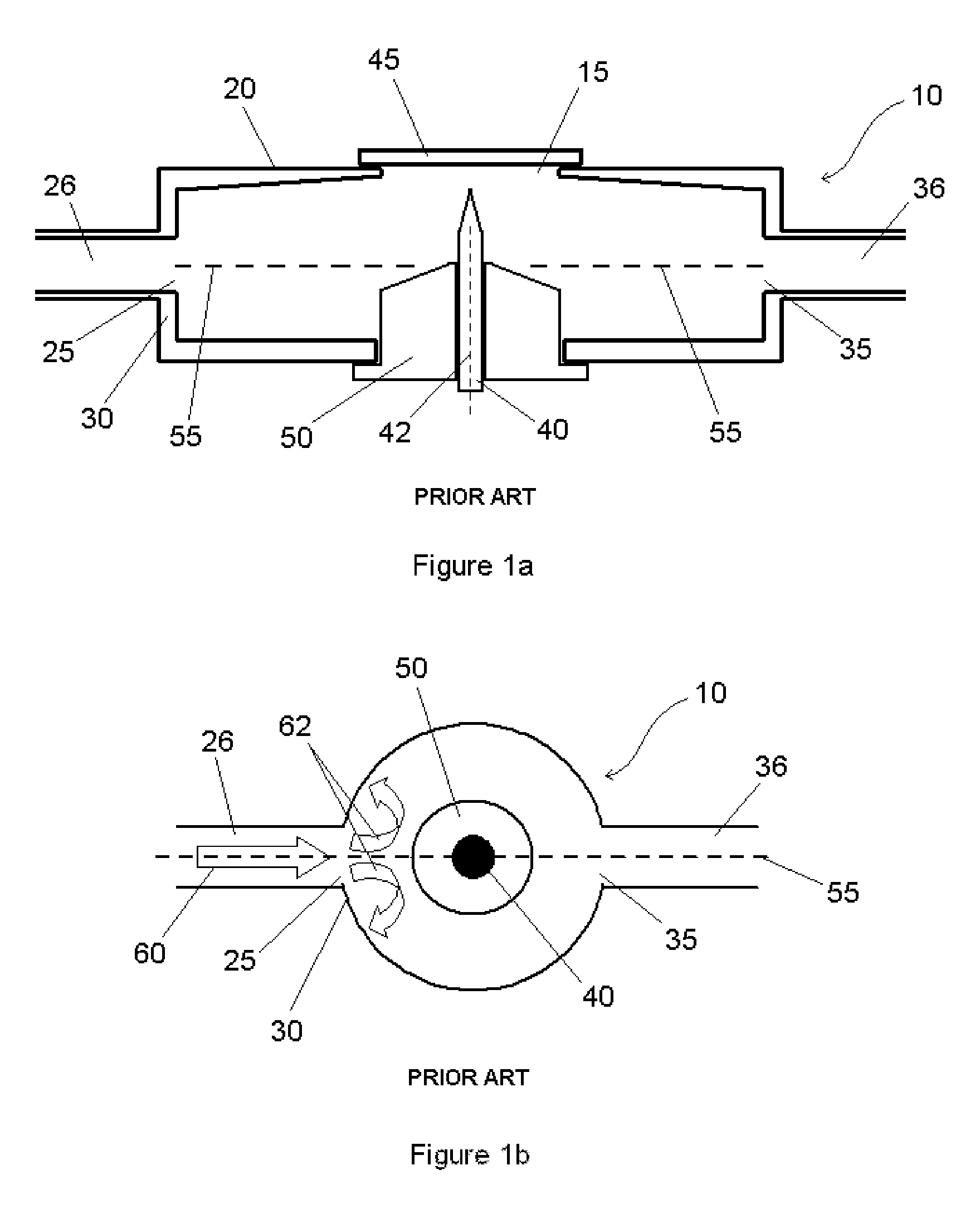
[0033]FIG. 1a shows a schematic cross-sectional side view of a prior art spark chamber of generally cylindrical geometry 10, comprising an aperture 15 in the top face 20 of the chamber 10. Gas inlet 25 adjoins the chamber on a curved sidewall 30 and gas outlet 35 adjoins the chamber on an opposing side. Gas inlet conduit 26 connects to gas inlet 25; gas outlet conduit 36 connects to gas outlet 35. Within the chamber is an elongated cylindrical electrode 40, the tapered conical end of which faces the centre of aperture 15. The cylindrical electrode 40 has an axis 42. In use, a sample 45 is mounted onto the chamber so that a face of the sample covers aperture 15. An electrical discharge is initiated between the electrode 40 and the sample to vaporise sample material, as previously described. Argon gas of purity better than 99.997% is fed into the chamber via the gas inlet 25 at a rate of 5 slpm (standard litres per minute) during sample analysis. The maximum unobstructed internal cros...


PUM

PropertyMeasurementUnit
wavelength rangeaaaaaaaaaa
gas flow rateaaaaaaaaaa

Abstract

A spark chamber for an optical emission analyser, comprising: a gas inlet located on a first side of the spark chamber for supplying a gas into the spark chamber; and a gas outlet located on a second side of the spark chamber arranged to convey the gas from the spark chamber; wherein an elongated electrode having an electrode axis generally along the direction of elongation is located within the spark chamber; and wherein: the first and second sides of the spark chamber lie at either side of the elongated electrode in directions generally perpendicular to the electrode axis; there is a gas flow axis through the spark chamber between the gas inlet and the gas outlet; and on passing along the gas flow axis from the gas inlet to the gas outlet the unobstructed internal cross sectional area of the spark chamber perpendicular to the gas flow axis remains constant to within a factor A, wherein A lies between 1.0 and 2.0

Description

FIELD OF THE INVENTION[0001]This invention relates to the field of spark optical emission spectrometry. Specifically the invention is concerned with an improved spark chamber for an optical emission spectrometer.BACKGROUND[0002]Spark optical emission spectrometry is a well known technique used to analyse solid samples. Optical emission spectrometry may be conducted with either a spark or arc for example. For convenience, as used herein, the term spark optical emission spectrometry means any optical emission spectrometry employing an electrical discharge to excite the sample such as a spark or arc for example, and the term spark chamber means a chamber for conducting any electrical discharge. A solid sample is typically mounted onto the table of a spark stand, also known as Petrey's stand. The spark stand further comprises a spark chamber, within which is an electrode oriented to present a tapered end towards the sample surface. The table of the spark stand has an aperture in the spa...

Claims


Application Information

Patent Timeline
Patent Type & Authority Patents(United States)
IPC IPC(8): G01J3/10G01N21/67G01J3/443G01N21/05
CPCG01J3/10G01N21/67G01J3/443G01N21/05
Inventor DORIER, JEAN-LUCDEMARCO, FABIOHALASZ, EDMUND
Owner THERMO FISHER SCI ECUBLENS
Why Eureka
Try Eureka