Flotation method

a technology of froth layer and flotation method, which is applied in the direction of liquid/fluent solid measurement, grain treatment, instruments, etc., can solve the problems of froth layer, coarse ore particles may not be able to travel all the way, etc., and achieves a higher overall recovery, lower concentrate grade, and greater mass pull

Active Publication Date: 2022-02-15
METSO OUTOTEC (FINLAND) OY
View PDF13 Cites 0 Cited by
  • Summary
  • Abstract
  • Description
  • Claims
  • Application Information

AI Technical Summary

Benefits of technology

[0003]The technical effects of the current disclosure include that by inducing an overflow of entrained slurry instead of a conventional froth overflow from the flotation cell or cells, coarse valuable ore particles may be recovered efficiently. Coarse ore particles which may initially adhere to the flotation gas bubbles may be too heavy for the flotation gas bubbles to lift them upwards by buoyancy or become lifted as gas bubble-ore particle agglomerates with the upwards flow of the slurry. Therefore coarse ore particles may not be able to travel all the way up to the froth layer at the top part of the flotation cell to be collected as froth overflow from the flotation cell as would happen to entrapped ore particles in a conventional froth flotation cell. Instead, the coarser particles may become detached from the bubbles and fall back down to the bottom part of the flotation cell, if the continuous upwards flow of slurry is not kept strong enough to carry the coarse particles upwards by the movement of the flow alone, without the help of the flotation gas bubbles. In a conventional froth flotation cell, the mixing inside the cell is strongest in the bottom region of the cell and slowly recedes towards the top of the cell. This drop off in slurry mixing and rising slurry velocity is deliberate so that the rising air bubbles with attached valuable particles can transfer into the froth zone and form a deep froth layer. However, coarse particles attached to air bubbles continue to rise up until they reach this pulp / froth interface. It is at this point where 80% of these coarse particles will drop off back into the pulp phase because of their low contact angle with the air bubble and subsequent loss of buoyancy as the draining froth phase cannot support their weight. This particle dropback occurs at the pulp / froth interface. Coarse particles have a low contact angle with gas bubbles so they are easily dislodged at the pulp / froth interface and by any excess turbulence in the flotation cell. By coarse particles herein is meant ore particles with a P80 of 200 μm to 2000 μm. It will be understood by one skilled in the art that P80 means that 80% of the particles pass through a nominated screen mesh size. For example, a P80=600 μm means that 80% of all particles present will pass through a 600 μm screen aperture.
[0058]By employing overflow flotation cells as described herein, it may be possible to have for example only two flotation lines comprising altogether 10 flotation cells (which include both the overflow type and conventional type of flotation cells) instead of a typical configuration of five flotation lines each equipped with seven cells, totaling 35 cells. In effect, utilising overflow flotation cells in the treatment system, savings in capital expenditure may be significant, especially in operations of low grade ore treatment.

Problems solved by technology

Therefore coarse ore particles may not be able to travel all the way up to the froth layer at the top part of the flotation cell to be collected as froth overflow from the flotation cell as would happen to entrapped ore particles in a conventional froth flotation cell.

Method used


Image

  • Flotation method
  • Flotation method
  • Flotation method

Examples


Embodiment Construction

[0065]Reference will now be made in detail to the embodiments of the present invention, examples of which are illustrated in the accompanying drawings.

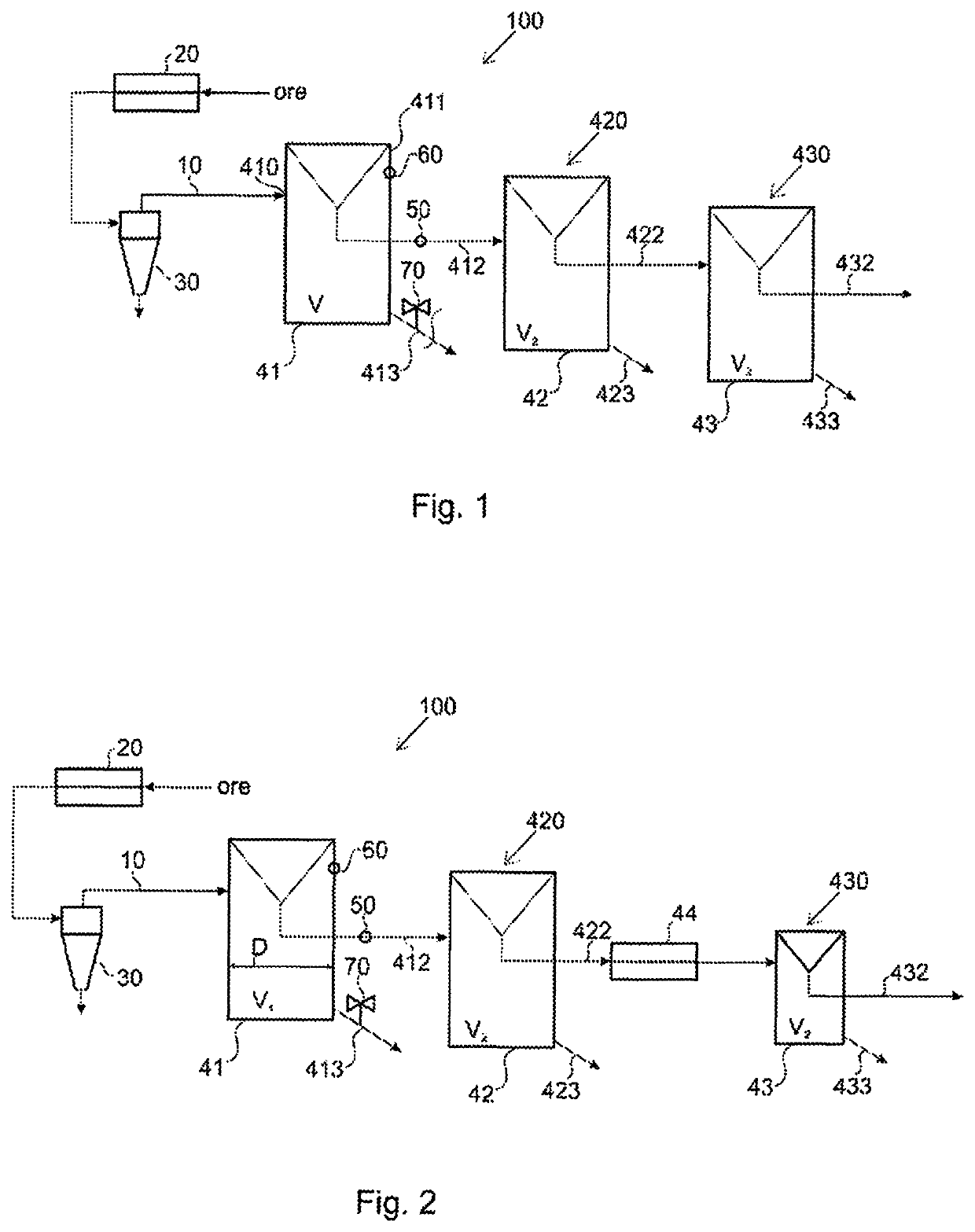
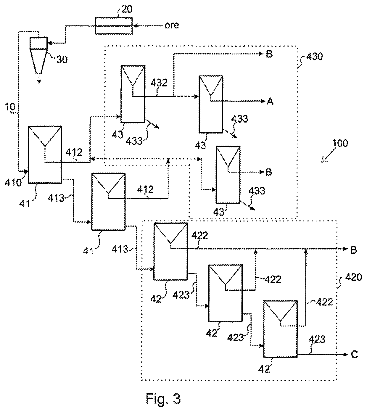
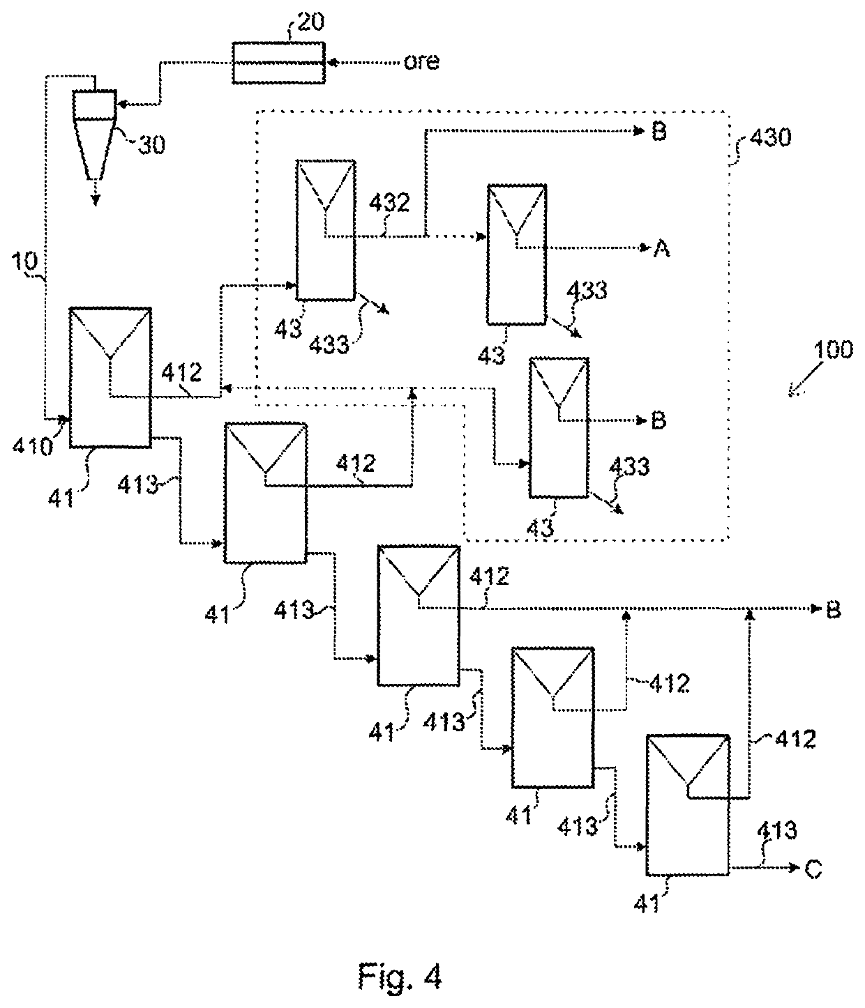
[0066]In FIGS. 1 to 4, a flotation cell 41 receives a flow of suspension, that is, a flow of slurry 410 comprising ore particles, water and flotation chemicals such as collector chemicals and non-collector flotation reagents. The collector chemical molecules adhere to surface areas on ore particles having the valuable mineral, through an adsorption process. The valuable mineral acts as the adsorbent while the collector chemical acts as the adsorbate. The collector chemical molecules form a film on the valuable mineral areas on the surface of the ore particle. The collector chemical molecules have a non-polar part and a polar part. The polar parts of the collector molecules adsorb to the surface areas of ore particles having the valuable minerals. The non-polar parts are hydrophobic and are thus repelled from water. The repelling cause...


PUM

PropertyMeasurementUnit
volumeaaaaaaaaaa
volumeaaaaaaaaaa
diameteraaaaaaaaaa

Abstract

A flotation method for recovering valuable metal containing ore particles from ore particles suspended in slurry is disclosed. In the method, the slurry is treated in an at least one overflow flotation cell and the valuable metal containing ore particles are recovered by conducting the continuous upwards flow of slurry out of the at least one overflow flotation cell as slurry overflow. At least part of the slurry overflow is conducted to a further treatment step in a treatment system.

Description

FIELD OF THE INVENTION[0001]The present invention relates to a flotation method for separating valuable metal containing ore particles from ore particles suspended in slurry.SUMMARY OF THE INVENTION[0002]According to the present invention, a flotation method is provided for recovering valuable metal containing ore particles from ore particles suspended in slurry. In the method, the ore particles are ground in a grinding step, classified in a classifier from which at least the overflow is conducted as a slurry feed to a treatment system comprising at least two flotation cells of which at least one is an overflow flotation cell operated with constant slurry overflow. The slurry is treated in the at least one overflow flotation cell by introducing flotation gas bubbles into the slurry and by creating a continuous upwards flow of slurry in the vertical direction of the first flotation cell. At least part of the valuable metal containing ore particles are adhered to the gas bubbles and r...

Claims


Application Information

Patent Timeline
Patent Type & Authority Patents(United States)
IPC IPC(8): B03D1/02G01F1/00B02C23/20G01F1/66G01F1/661
CPCB03D1/028B02C23/20B03D1/02G01F1/00G01F1/661B03D2203/025Y02P10/20
Inventor RINNE, ANTTIBOURKE, PETER GERARD
Owner METSO OUTOTEC (FINLAND) OY
Why Eureka
Try Eureka