Method for manufacturing a component of austenitic TWIP or TRIP/TWIP steel

Active Publication Date: 2022-02-15
OUTOKUMPU OY
View PDF28 Cites 2 Cited by
  • Summary
  • Abstract
  • Description
  • Claims
  • Application Information

AI Technical Summary

Benefits of technology

[0007]The object of the present invention is to eliminate some drawbacks of the prior art and to achieve a method for manufacturing a component of an austenitic steel which not only have effect to the

Problems solved by technology

Further, the WO publication 2014/096180 does not teach anything how to bypass

Method used


Image

  • Method for manufacturing a component of austenitic TWIP or TRIP/TWIP steel
  • Method for manufacturing a component of austenitic TWIP or TRIP/TWIP steel

Examples


Embodiment Construction

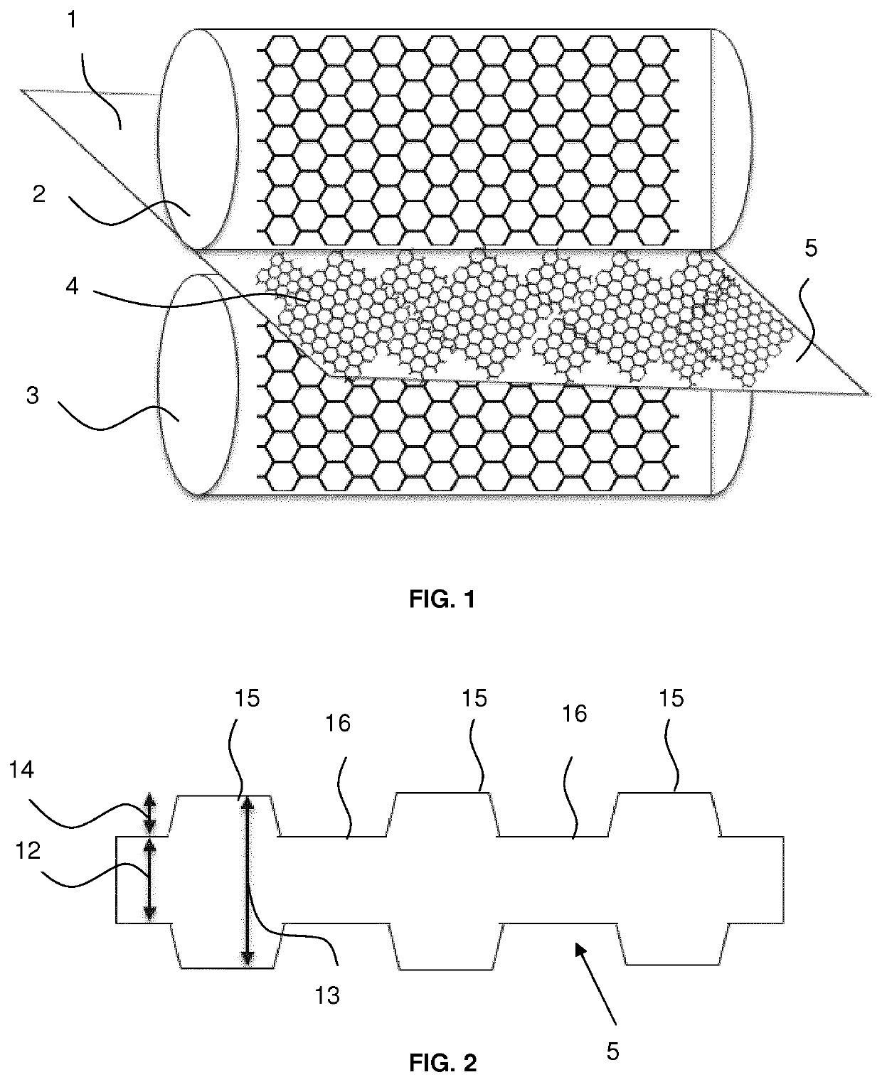
[0025]The material of the FIGS. 1-4 is an austenitic stainless steel having the TWIP effect and containing as the main components with iron in weight % 0.3 carbon, 16% manganese, 14% chromium, less than 0.5% nickel and 0.3% nitrogen.

[0026]According to FIG. 1 a flat strip 1 is running through a cold rolling mill, which is illustrated by the working rolls 2 and 3. The rolls 2 and 3 are profiled to create indentations both in the direction transverse to the rolling direction and in the direction parallel to the rolling direction which indentations form a honeycomb structure 4 on the surfaces of the deformed strip 5.

[0027]In FIG. 2 it is shown one part of the deformed strip 5 of FIG. 1. The initial thickness of the flat strip is shown as the reference number 13 and the depth of an indentation, with the value of 30%, as the reference number 14. The deformed strip 5 with the deformed thickness 12 has on the surfaces non-deformed areas 15 with high ductility and high elongation. The indent...


PUM

PropertyMeasurementUnit
Temperatureaaaaaaaaaa
Fractionaaaaaaaaaa

Abstract

The present invention relates to a method for manufacturing a component of austenitic TWIP or TRIP/TWIP steel. A flat product (1) is deformed by achieving at least one indentation (16) on at least one surface of the flat product (1) in order to have in the deformed product (5) areas of a high strength steel embedded in a matrix of a ductile material. The invention also relates to the use of the component where areas of a high strength steel embedded in a matrix of a ductile material are required in the same component.

Description

CROSS-REFERENCE TO RELATED APPLICATIONS[0001]This application is the United States national phase of International Application No. PCT / EP2016 / 066318 filed Jul. 8, 2016, and claims priority to European Patent Application No. 15176945.2 filed Jul. 16, 2015, the disclosures of which are hereby incorporated in their entirety by reference.BACKGROUND OF THE INVENTION[0002]Field of the Invention[0003]The present invention relates to a method for manufacturing a component of austenitic TWIP or TRIP / TWIP steel. The indentations are achieved by deforming a flat product of steel in that area of the steel material desired for the utilization of the component.[0004]Description of Related Art[0005]Before manufacturing components for transport systems such as cars, trucks, busses, railway or agricultural vehicles, it shall be calculated how much strength and material thickness is needed for fulfilling the safety requirements. But when there are components which have a higher material thickness tha...

Claims


Application Information

Patent Timeline
IPC IPC(8): B21B1/22B21H8/00C21D1/02C21D7/04C22C38/04B21B27/00B21C37/02
CPCB21B1/227B21B27/005B21C37/02B21H8/005C21D1/02C21D7/04C22C38/04B21B2001/221C21D2211/001
Inventor FRÖHLICH, THOMASLINDNER, STEFAN
Owner OUTOKUMPU OY
Why Eureka
Try Eureka