Surface light source LED device

a led light source and surface technology, applied in semiconductor devices, light source combinations, vehicle lamps, etc., can solve the problems of less design space, large structure and less design space, and the inability to use light diffusion materials in vehicle lamps requiring a greater led light, etc., to achieve the effect of satisfying the light distribution requirements, thin thickness and narrow width

Active Publication Date: 2022-02-15
EXCELLENCE OPTO INC
View PDF10 Cites 1 Cited by
  • Summary
  • Abstract
  • Description
  • Claims
  • Application Information

AI Technical Summary

Benefits of technology

[0018]In response to the above-referenced technical inadequacies, the present disclosure discloses constructs and manufacturing techniques of a surface light source LED device that is a wide-angle surface light source LED device capable of emitting a visually uniform light. The wide-angle surface light source LED device is formed by disposing one or a plurality of LED bar elements on a carrier surface or a circuit board. The LED bar element has a plurality of LED bars disposed therein, each of the plurality of LED bars includes a plurality of LED dies, and the LED dies can be disposed tightly in a straight, arced, or curved arrangement. For achieving a visually uniform light-emitting effect, in principal the LED dies are arranged with an interval no greater than 2 mm. The LED bar has a primary lens structure having features of extremely thin thickness and narrow width.
[0019]The wide-angle surface light source LED device emits light along a strip direction (also known as a longitudinal direction), so as to present a visual continuity and uniform distribution. Through the staggered arrangement of the plurality of LED bar elements, an effect of uniform surface light source is presented. Another feature of the lighting device is that, a special primary lens design of the LED bars can be utilized to effectively satisfy the light distribution requirements of lamp application (such as vehicle lamps). For application fields regarding streamlined vehicle lamp design adopting a transparent light guiding plate, in the wide-angle surface light source LED device of the present disclosure, due to the tight arrangement of light-emitting LED dies, a requirement of a more visually uniform light emittance light source can be met. Since the wide-angle surface light source LED device of the present disclosure has the primary lens structure and has features of extremely thin thickness and narrow width, the light emitted therefrom can be effectively incident into the transparent light guiding plate, thereby satisfying the light distribution requirements of the vehicle lamp.
[0020]The goals of the present disclosure are not limited to using small size LED dies as a surface light source and proceed to design the primary optics lens to acquire the primary lens structure that is smaller in size, higher in light usage efficiency and precise in control, so that when applying the present disclosure in the field of vehicle lamp, an issue of an excessively wide light strip being unable to match a narrower light guiding plate can be solved, and an issue of an excessively thick light strip being unable to fit into a narrower lamp body space can be solved. The present disclosure can also solve the technical difficulties of being unable to achieve a larger surface light source area with a smaller quantity of LED. Moreover, the present disclosure can also satisfy rules and regulations related to light distribution that request a higher luminosity on a center and peripheral area. The present disclosure provides symmetric illumination patterns, so an excessively large illumination output is not needed. Energy consumption does not become an issue in the present disclosure, nor does a complex design or large size of a heat sink due to excessive energy consumption. The present disclosure also solves an issue of visually uneven distribution of light and shade, or non-uniform surface light source from lamps of existing technologies adopting LED as a light source, and effectively improves and elevates the quality of the lamp body. Therefore, the present disclosure is capable of completely satisfying the market requirements of the vehicle lamp presenting an elevated water clear quality.

Problems solved by technology

Disadvantages: direct illumination LED light sources are not a uniform light source.
Disadvantages: the vehicle lamp using LED in combination with light diffusion materials has issues of larger structure and less space for design, due to light intensity attenuation by diffusion materials, and the light diffusion materials cannot be used in a vehicle lamp requiring a greater LED light intensity
Disadvantages: limitations and issues of the OLED include low production volume, high cost of a customized light source using OLED light as the cost of using OLED is generally five times higher than that of using a common LED, and OLED has a short life expectancy.
Regarding the U.S. Pat. No. 8,497,519 related to the uniform surface light source, entitled “BATWING LED WITH REMOTE PHOSPHOR CONFIGURATION”, the technical disadvantages disclosed in this specification are as follows: 1. The mold for producing the lens has a limited form, and LED dies are limited to be in a rectangular arrangement and cannot be flexibly adjusted for various types of a customized lamp; 2. The production process is complex and cannot be simplified, and lacks a consideration for the economic value.
Regarding the U.S. Pat. No. 8,382,337, entitled “LIGHTING DEVICE, LIGHT SPREADING PLATE AND METHOD FOR MANUFACTURING THE SAME”, the technical disadvantages disclosed in this specification are as follows: 1. This specification does not have a linear arrangement, and is difficult to meet the requirements of appearance of the customized lamp; 2. This specification does not have a better diffusion effect of a wide-angle uniform surface light source; 3. This specification uses more LED dies; 4. When this specification is applied to the vehicle lamp, a uniformity requirement of not visually perceiving a particle light source cannot be satisfied.

Method used


Image

  • Surface light source LED device
  • Surface light source LED device
  • Surface light source LED device

Examples


first embodiment

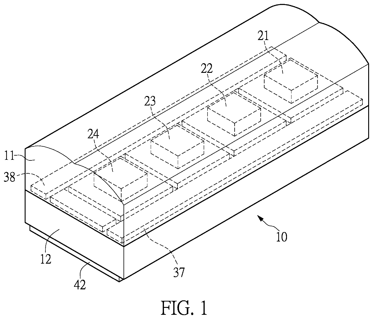
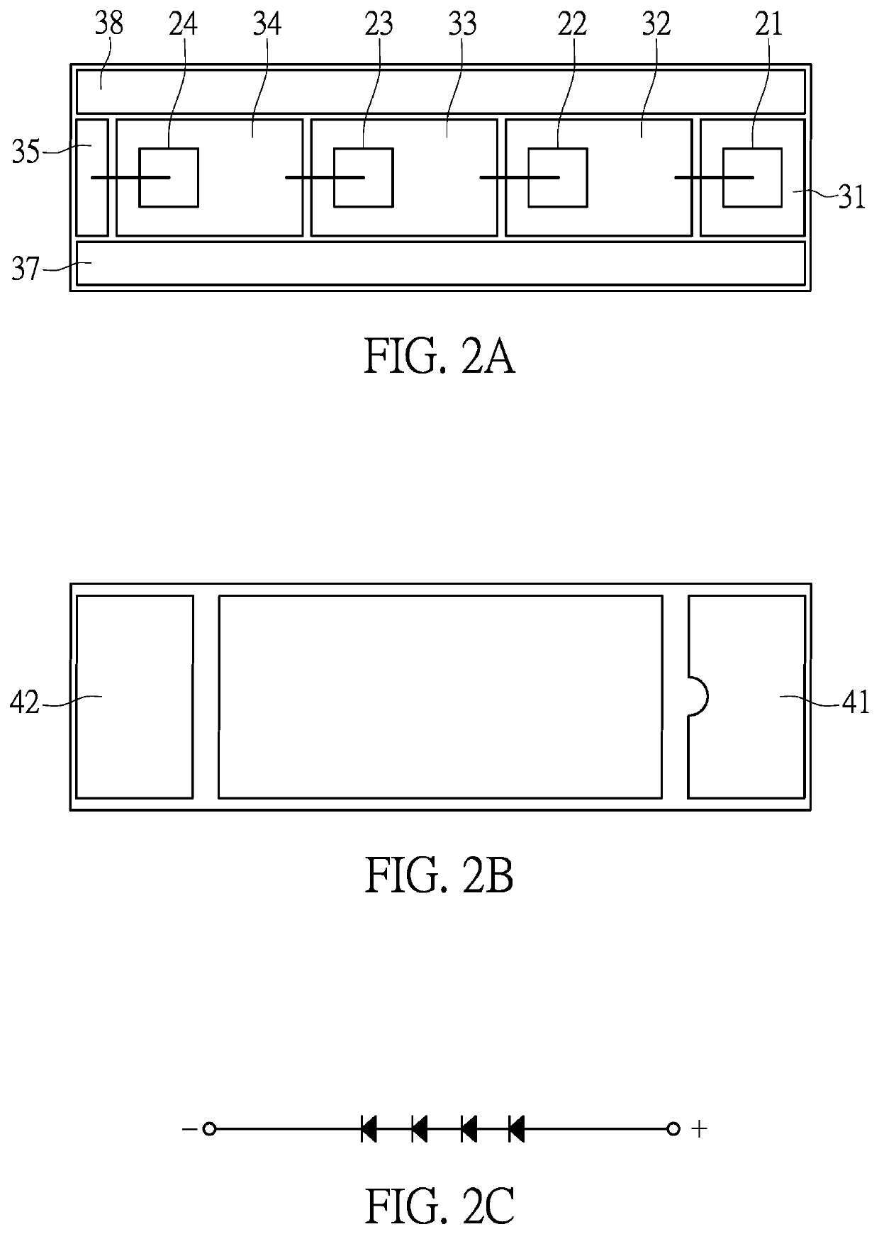
[0045]Reference is made to FIG. 1, which is a perspective schematic view of a first embodiment of the present disclosure, in which the structure of an LED bar 10 is disclosed, the LED bar 10 includes a substrate 12 and a wide-angle lens 11; and a plurality of die areas and a plurality of electrode areas are arranged on an upper surface of the substrate 12, and a plurality of LED dies are respectively arranged corresponding to the plurality of die areas disposed on the substrate 12. The wide-angle lens 11 is covered upon the plurality of die areas, the plurality of electrode areas and the plurality of LED dies. In practical operation, the substrate 12 may be a printed circuit board (PCB), a flexible printed circuit board (FPCB) or a multilayer printed circuit board, and related descriptions of the plurality of die areas and the plurality of electrode areas will be iterated in detail in FIG. 2A.

[0046]In FIG. 1, the wide-angle lens 11 is covered upon a plurality of LED dies 21 to 24 an...

second embodiment

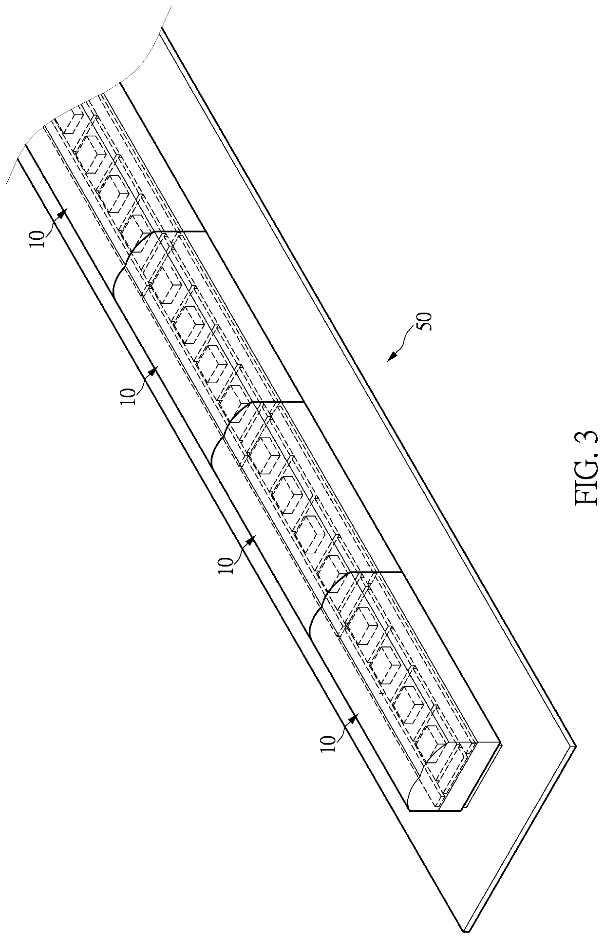
[0054]Reference is made to FIG. 3, which is a perspective view of a structure of the LED bar element 50 of a second embodiment of the present disclosure. The plurality of LED bars 10 are linearly arranged on a carrier platform, the carrier platform may be a circuit board or a flexible circuit board, a plurality of connection wires may be disposed on the flexible circuit board so that the plurality of LED bars 10 may be electrically connected with external control circuits. It should be particularly noted that, intervals between the plurality of the LED bars 10 are the same as the equal intervals between the plurality of LED dies 21 to 24. As shown in FIG. 3, the LED bar element 50 has a strip structure, and the strip structure is a straight strip structure. In practical applications, the LED bar element 50 shown in FIG. 3 is also one of the embodiments of the wide-angle surface light source LED device of the present disclosure.

third embodiment

[0055]Reference is made to FIG. 4, which is a perspective view of a structure of a LED bar element 60 of a third embodiment of the present disclosure. A plurality of LED bars 10a are arranged on a carrier platform in a linear bent (or arced) manner, the carrier platform may be a circuit board or a flexible circuit board, the plurality of connection wires may be disposed on the flexible circuit board so that the plurality of LED bars 10a may be electrically connected with external control circuits. It should be particularly noted that, intervals between the plurality of the LED bars 10a are the same as the equal intervals between the plurality of LED dies 21 to 24. As shown in FIG. 4, the LED bar element 60 has a strip structure, and the strip structure is an arced strip structure. A structural shape of the arced strip structure can be bent along a left or a right direction, can be partially straight and partially bent, and can be continuously bent to present a shape of “S”, and the ...


PUM

PropertyMeasurementUnit
lengthaaaaaaaaaa
heightaaaaaaaaaa
viewing angleaaaaaaaaaa

Abstract

A surface light source LED device includes a circuit board, at least one power input and at least two LED bar elements, the at least two LED bar elements are arranged in a staggered manner, and each of the LED bar elements includes a plurality of LED bars arranged linearly on the circuit board. Each of the LED bars has a straight strip structure and has a plurality of LED dies of the same type provided inside. The plurality of LED dies is arranged linearly at equal intervals.

Description

FIELD OF THE DISCLOSURE[0001]The present disclosure relates to a surface light source LED device, and more particularly to a LED device that can be used as wide-angle surface light sources of various structures for a vehicle lamp.BACKGROUND OF THE DISCLOSURE[0002]In existing technologies, with features such as high-luminance, energy-saving, multi-color, and fast-changing, LED has been widely applied in technical fields of lighting that require light sources. In the field of vehicle lamp, LED has become the most prominent light source. It is widely known that during a process of driving a vehicle, besides providing necessary road lighting, another important function of a vehicle lamp is to emit signals (signs) or warnings to other vehicles or pedestrians for raising awareness of safety. In a functional perspective, vehicle signal lamps mainly include position lights, turn signal light, and brake lights.[0003]As the brand recognition has become more sought after, signal lights of the ...

Claims


Application Information

Patent Timeline
Patent Type & Authority Patents(United States)
IPC IPC(8): F21S4/22F21S41/143F21S41/176F21S43/14F21S43/16F21S41/26F21Y113/10F21Y115/10
CPCF21S4/22F21S41/143F21S41/176F21S41/26F21S43/14F21S43/16F21Y2113/10F21Y2115/10F21S41/151F21S43/15F21S41/25F21S43/26F21V23/003F21W2107/10H01L25/0753H01L33/58H01L33/60H01L33/50H01L33/62F21Y2105/18F21Y2103/10
Inventor SHEN, WEI-POLAI, CHUN-MINGCHANG, CHIH-CHIANGHUANG, WEN-HSINGTSAI, TZENG-GUANGHUANG, KUO-HSIN
Owner EXCELLENCE OPTO INC
Why Eureka
Try Eureka