
Line supply arrangement

a line supply and line technology, applied in the direction of trolley lines, power rails, electric vehicles, etc., can solve the problems of tripping hazards for users of charging stations, permanent damage to the line, and the inability to set up a conventional charging station near the vehicle, so as to increase complexity, and reduce the risk of tripping

Active Publication Date: 2022-03-08
STEMMANN TECHN
View PDF18 Cites 0 Cited by
  • Summary
  • Abstract
  • Description
  • Claims
  • Application Information

AI Technical Summary

Benefits of technology

The invention is a power supply arrangement for electric vehicles that allows for flexible and efficient charging without the need for direct contact with the ground. The line is supported and led from above, making it easier to position horizontally across the vehicle. The line is also liquid-cooled, which makes it lighter, flexible, and easier to handle. The cross-section of the line can be increased to transmit more current, and the line can be retracted to prevent collisions with the vehicle. The power supply arrangement includes a hose reel for supplying and discharging cooling liquid to the line, and the support arm acts like a boom of a tower crane, allowing for flexibility and maneuverability. Overall, the invention provides a more efficient and safe means for charging electric vehicles.

Problems solved by technology

This can lead to permanent damage to the line.
In addition, a conventional charging station may often not be set up near the vehicle, either because there is not enough space or because the charging station can be hit or knocked over by the commercial vehicle.
The charging line is a tripping hazard for the user of the charging station.
It should also be taken into account that the large line cross-sections render handling of the lines very difficult.
However, the cooling renders the line slightly bulkier.

Method used


Image

  • Line supply arrangement
  • Line supply arrangement
  • Line supply arrangement

Examples


Embodiment Construction

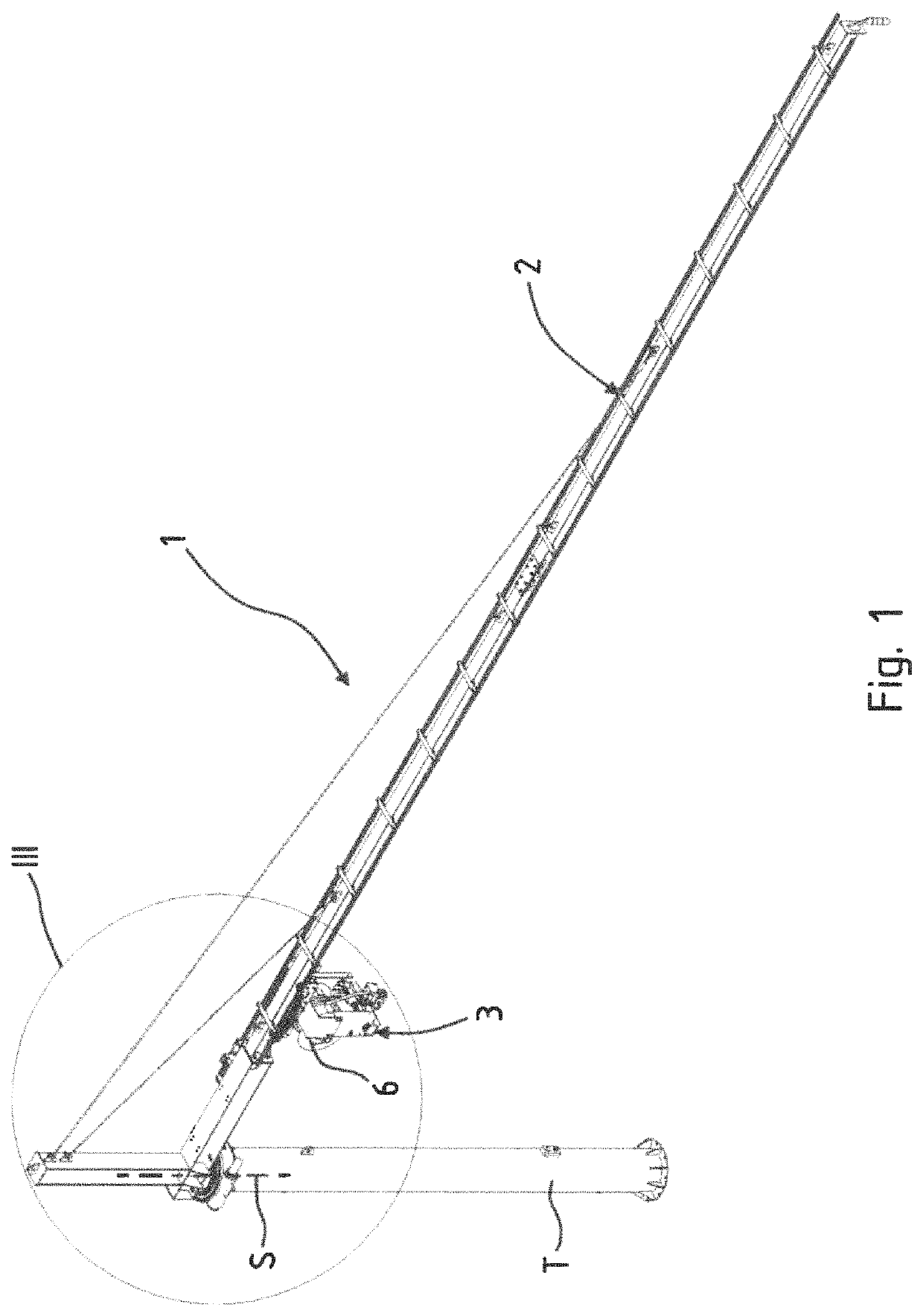
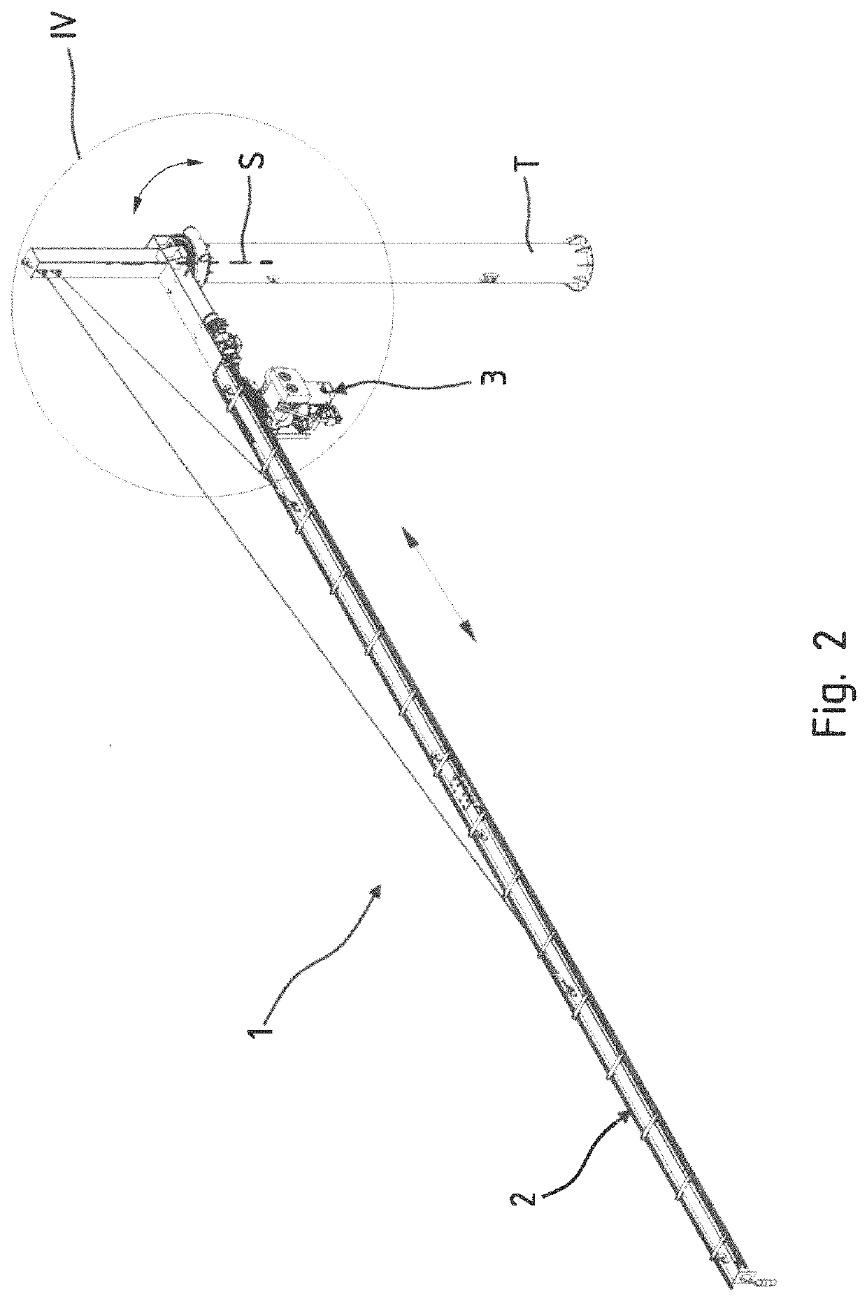
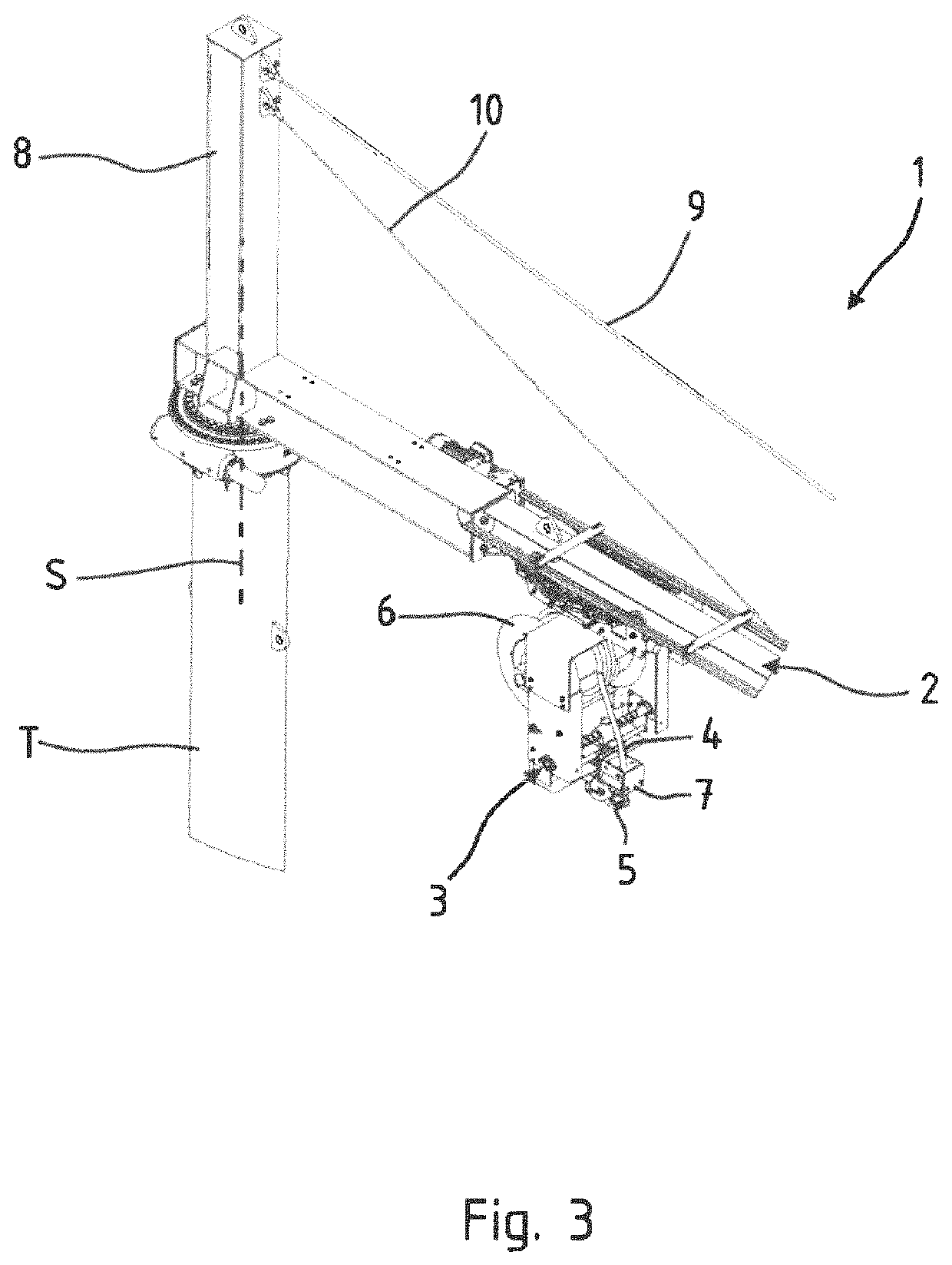
[0035]The line supply arrangement 1 according to FIGS. 1 to 4 is used to provide electrical energy to an electrically operated motor vehicle, not shown in detail, for charging its energy store. The electric motor vehicle is in particular a car or a truck, in particular a commercial vehicle. The motor vehicle involved here is a motor-driven vehicle that is not bound to rails, i.e. a motor vehicle, a motorcycle or a tractor.

[0036]The line supply arrangement 1 includes a support arm 2 which is secured to a support column T. The support arm 2 is secured to the upper end of the support column T so as to be arranged at a distance from the base of the support column T to permit the motor vehicle to be charged to travel under the support arm 2.

[0037]The support arm 2 is longer than the support column T is high. It has a length of at least 4 m, preferably even at least 8 m.

[0038]Located on the support arm 2 is a trolley 3 which is movable in longitudinal direction of the support arm 2. The t...


PUM


Abstract

A line supply arrangement for electrically powered motor vehicles includes an electric line on a support arm above the motor vehicle. A trolley on the support arm positions the electric line such that a free end thereof hangs down from the trolley for connection to the motor vehicle and charging of an energy store. The trolley is movable relative to the support arm in horizontal direction or the support arm is movable and the trolley relative to the support arm in horizontal direction. Arranged on the trolley is a line reel to lower the free end of the electric line to the motor vehicle, and a hose reel is fixed on the support arm for supply and discharge of cooling liquid to and from the electric line. The trolley is movable relative to the hose reel. A heat exchanger is arranged distal to the trolley for cooling the cooling liquid.

Description

CROSS-REFERENCES TO RELATED APPLICATIONS[0001]This application is the U.S. National Stage of International Application No. PCT / DE2019 / 100805, filed Sep. 9, 2019, which designated the United States and has been published as International Publication No. WO 2020 / 057693 and which claims the priority of German Patent Application, Serial No. 10 2018 122 863.2, filed Sep. 17, 2018, pursuant to 35 U.S.C. 119(a)-(d).BACKGROUND OF THE INVENTION[0002]The invention relates to a line supply arrangement.[0003]Electrically powered motor vehicles, in particular commercial vehicles and cars, must regularly drive to charging stations or be called back to a depot in order to be charged there. If it is possible, not only during downtimes at night, but, e.g., also during loading and unloading a truck, a moving line is connected to the motor vehicle in order to charge the batteries.[0004]Loading and charging times of commercial vehicles are normally short in order to fully charge a battery. The more cur...

Claims


Application Information

Patent Timeline
Patent Type & Authority Patents(United States)
IPC IPC(8): B60L53/35B60L53/18B60L53/302B60M1/30B60M1/12
CPCB60L53/18B60L53/302B60M1/12B60M1/307B60L53/35H02G11/02H02G11/006B60L53/14B60L53/31Y02T10/70Y02T10/7072Y02T90/14Y02T90/12
Inventor BÜNKER, LUDGEREVENBLIJ, SIMON HENDRIK
Owner STEMMANN TECHN
Learn More