Electric reaction control system

a technology of reaction control and electric aircraft, which is applied in the direction of machine/engine, aircraft navigation control, vertical landing/take-off aircraft, etc., can solve the problems of increased aircraft weight, complex control, and inability of lift nozzles to provide precise roll, pitch and yaw attitude control of aircraft, etc., to facilitate in-flight trajectory modifications and minimize the moment of inertia

Active Publication Date: 2020-11-10
TEXTRON INNOVATIONS
View PDF8 Cites 0 Cited by
  • Summary
  • Abstract
  • Description
  • Claims
  • Application Information

AI Technical Summary

Benefits of technology

[0005]An electric reaction control system is disclosed that can selectively expel a “burst” or “puff” of air to alter the orientation of the aircraft during flight. The present disclosure incorporates ducting, an air compressor, an electric motor, a plurality of nozzles in an aircraft to facilitate the in-flight trajectory modifications. VTOL aircraft cannot use surfaces to change its trajectory due to a lack of airflow over the surfaces. Ideally, the thrust is placed at the tips of the aircraft, where the greatest moment arm exists, with the mass as close to the center of the aircraft as possible to minimize the moment of inertia to either pitch, roll, or yaw the aircraft.
[0006]An agile aircraft should have the center of mass very close in, with very low inertia. Typical electric aircraft solutions to the agility include disposing propellers at the far ends of the aircraft. Electric aircraft have no source of “bleed” air, generated by a jet engine, to leverage in positioning the aircraft. The present disclosure implements an electric motor with an air compressor to generate “bleed” air. Advantageously, the electric reaction control system (ERCS) can support an unconventional aircraft where you had the lift system for the propulsion close to the center of the aircraft with nozzles at the extremities of the aircraft for control, which makes this aircraft ideal for high speed missions. Typically, most electric aircraft cannot attain high speeds due to the rotor configurations. The ERCS could facilitate an electric aircraft that would be very agile and very light, utilizing electric power, as opposed to jet power.

Problems solved by technology

However, integrating both lift and attitude control functions into the lift fans results in increased aircraft weight, rotational inertia, complexity of controls, and compromised airplane mode aerodynamics.
The lift nozzles however are incapable of providing precise roll, pitch and yaw attitude control of the aircraft necessary for vertical flight.
However, with the fans positioned close to the fuselage their effective moment is reduced to where they cannot provide adequate attitude control authority.
Incorporating a jet engine powered bleed air control system similar to the Harrier aircraft is problematic on a lift fan aircraft.
Turboshaft engines of the configuration used to power the lift fans are incapable of providing adequate air mass flow for bleed air control systems.
Additionally, any bleed air drawn from a conventional turboshaft engine significantly reduces the engines total power output.
Further, future lift fan aircraft utilizing electric propulsion to power fans will not have an existing source of bleed air to support a Harrier design control system.
VTOL aircraft cannot use surfaces to change its trajectory due to a lack of airflow over the surfaces.
Typically, most electric aircraft cannot attain high speeds due to the rotor configurations.

Method used


Image

  • Electric reaction control system
  • Electric reaction control system
  • Electric reaction control system

Examples


Embodiment Construction

[0014]The preferred version of the inventions presented in the following written description and the various features and advantageous details thereof are explained more fully with reference to the non-limiting examples included in the accompanying drawings and as detailed in the description which follows. Descriptions of well-known components are omitted so as to not unnecessarily obscure the principle features of the invention as described herein. The examples used in the following description are intended to facilitate an understanding of the ways in which the invention can be practiced and to further enable those skilled in the art to practice the invention. Accordingly, these examples should not be construed as limiting the scope of the claimed invention.

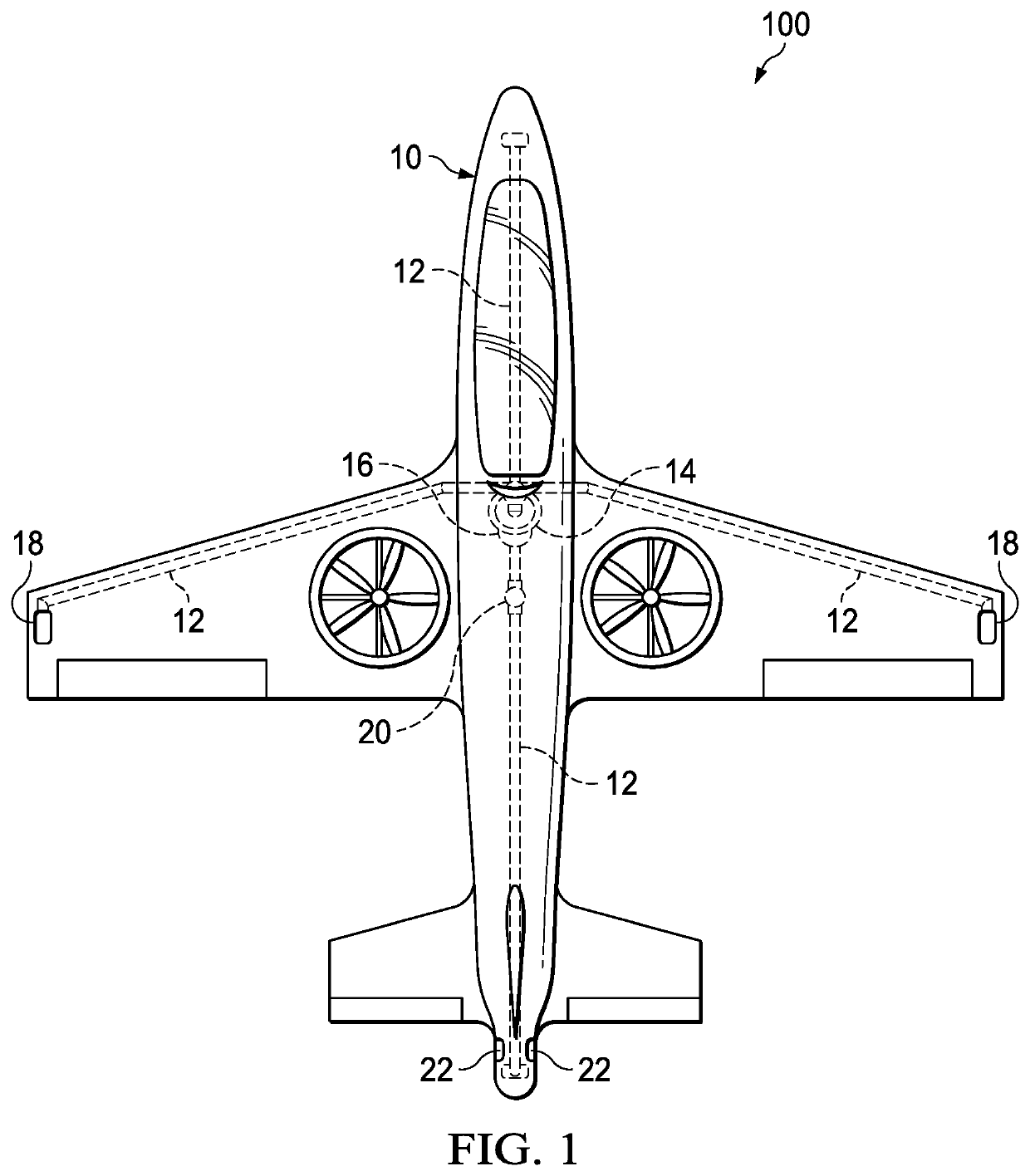
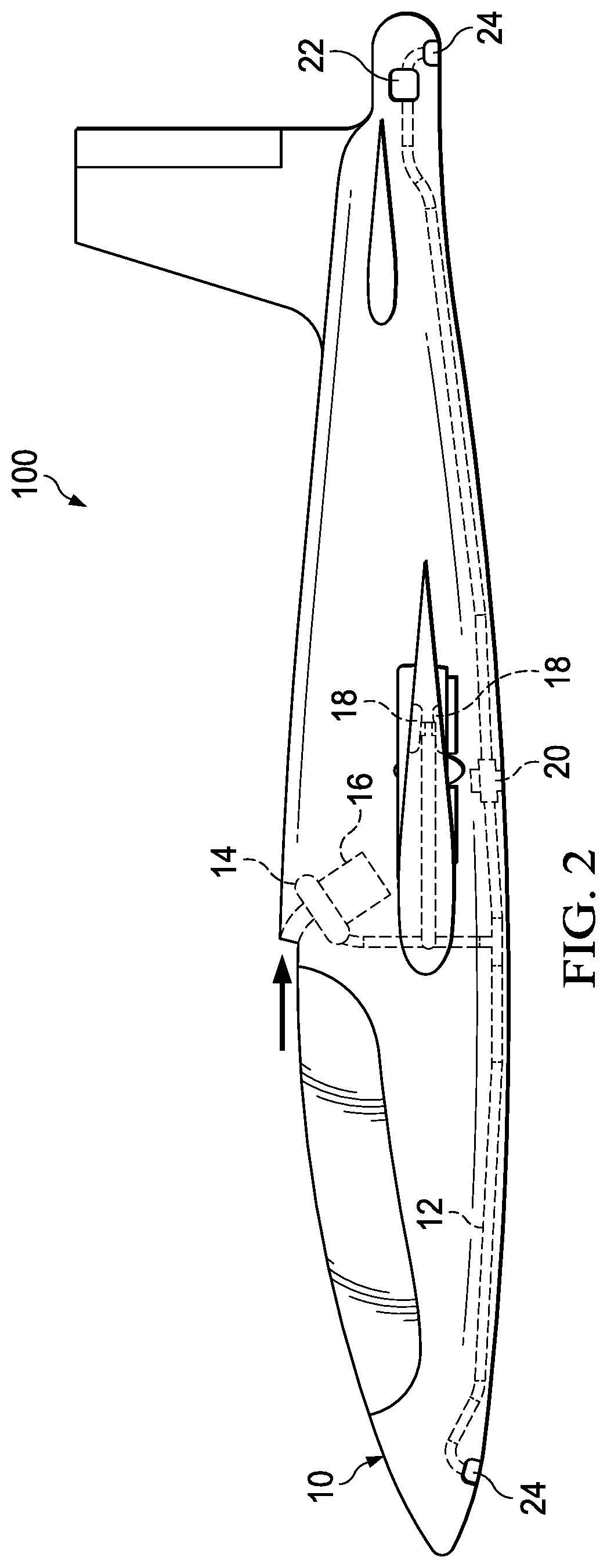
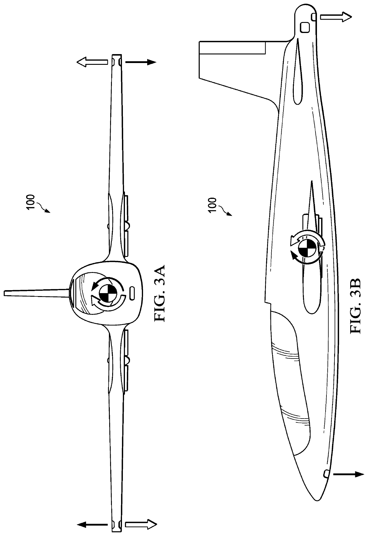
[0015]FIG. 1 is a schematic top view of an electric reaction control system, generally designated as 100, in accordance with an embodiment of the present disclosure. An electric reaction control system (ERCS) 100 can include an...


PUM


Abstract

An electric reaction control system that can selectively expel a “burst” or “puff” of air to alter the orientation of the aircraft during flight. An aircraft incorporating ducting, an air compressor, an electric motor, and a plurality of nozzles can facilitate in-flight trajectory modifications. When an air burst is needed to provide thrust for the purposes of reaction control, nozzles are selectively opened and closed to provide roll, pitch, and yaw of the aircraft. The ERCS can facilitate an electric aircraft that would be very agile and very light, utilizing electric power, as opposed to jet power.

Description

BACKGROUND1. Field of the Invention[0001]The present invention is generally related to electric aircraft and hybrid electric aircraft, and more specifically to electric and hybrid electric Vertical Take Off and Landing aircraft utilizing air bursts to alter the orientation of the aircraft during vertical flight.2. Background of the Invention and Description of Related Art[0002]Past and present aircraft configurations utilizing lift fans to achieve both Vertical Take Off and Landing (VTOL) and airplane mode capabilities position their fans at the extreme corners of the airframe to achieve attitude control. This positioning maximizes the effective moment of the fans to achieve an acceptable level of attitude control authority. However, integrating both lift and attitude control functions into the lift fans results in increased aircraft weight, rotational inertia, complexity of controls, and compromised airplane mode aerodynamics. Two prior art examples of this configuration are the Do...

Claims


Application Information

Patent Timeline
Patent Type & Authority Patents(United States)
IPC IPC(8): B64C29/00B64C19/00F04D25/06B64C15/14
CPCB64C29/0016B64C15/14F04D25/06Y02T50/10
Inventor FENNY, CARLOSKIM, SUNGCAMPBELL, KIPCHOI, JOUYOUNG JASON
Owner TEXTRON INNOVATIONS
Why Eureka
Try Eureka