Electrical switching apparatus contact assembly and movable contact arm therefor

Active Publication Date: 2007-05-15
EATON INTELLIGENT POWER LIMITED
View PDF18 Cites 26 Cited by
  • Summary
  • Abstract
  • Description
  • Claims
  • Application Information

AI Technical Summary

Benefits of technology

[0011]These needs and others are met by embodiments of the invention which are directed to a movable contact arm for the contact assembly of an electrical switching apparatus, such as a circuit breaker. For example, through the use of lightweight, high-strength material(s), and by optimizing the size and shape of the movable contact arm to minimize the moment-of-inertia of the arm, the angular opening velocity of the arm is increased, thus improving the performance of the circuit breaker. The length of the arm may also be increased to increase the space or gap between the movable and fixed contacts of the contact assembly to further improve the circuit interruption performance of the electrical switching apparatus.
[0012]As one aspect of the invention, a movable contact arm is provided for a contact assembly of an electrical switching apparatus. The electrical switching apparatus includes a housing which encloses the contact assembly. The contact assembly includes a fixed contact and a movable contact separable from the fixed contact in response to a trip condition. The movable contact arm comprises: a first end structured to carry the movable contact of the contact assembly; a second end disposed distal from the first end; a pivot portion proximate the second end, the pivot portion having a first width; and a moving arm portion generally extending from the first end toward the pivot portion, the moving arm portion having a second width, wherein the movable contact arm has a moment-of-inertia and an angular opening velocity, and wherein the second width of the moving arm portion of the movable contact arm is less than the first width of the pivot portion of the movable contact arm, in order to minimize the moment-of-inertia of the movable contact arm, thereby increasing the angular opening velocity.
[0016]As another aspect of the invention, a contact assembly is provided for an electrical switching apparatus including a housing, a line conductor and a load conductor both structured to be housed by the housing, and an operating mechanism. The contact assembly comprises: a fixed contact structured to be electrically connected to one of the line conductor and the load conductor; a movable contact structured to be electrically connected to the other of the line conductor and the load conductor; and a movable contact arm comprising: a first end, the movable contact of the contact assembly being mounted at or about the first end of the movable contact arm, a second end disposed distal from the first end of the movable contact arm, a pivot portion proximate the second end of the movable contact arm, the pivot portion of the movable contact arm having a first width, and a moving arm portion generally extending from the first end of the movable contact arm toward the pivot portion of the movable contact arm, the moving arm portion of the movable contact arm having a second width, an upper edge, a lower edge, and a height, the height being defined by the distance between the upper edge of the moving arm portion of the movable contact arm and the lower edge of the moving arm portion, wherein the movable contact arm is operable between a closed position in which the movable contact of the contact assembly is in electrical contact with the fixed contact of the contact assembly, and an open position in which the movable contact arm and the movable contact disposed thereon are spaced from the fixed contact of the contact assembly, wherein in response to a trip condition, the operating mechanism of the electrical switching apparatus separates the movable contact from the fixed contact and pivots the movable contact arm from the closed position toward the open position at an angular opening velocity, wherein the movable contact arm has a moment-of-inertia, and wherein the height of the moving arm portion of the movable contact arm is at least about four times the second width of the moving arm portion, in order to minimize the moment-of-inertia of the movable contact arm, thereby increasing the angular opening velocity.

Problems solved by technology

This undesirably adds weight, thus increasing the moment-of-inertia of the movable contact arm 16 and decreasing the performance of the circuit breaker 2.
Previously, this has not been possible because material strength and thermal requirements have dictated the size and geometry of the movable contact arm 16.
The foregoing results in the weight and the movement-of-inertia of the movable contact arm 16 being greater than desired, and the aerodynamic efficiency of the movable contact arm 16 being less than desired, thus adversely affecting the angular opening velocity of the movable contact arm 16 and inhibiting the circuit interruption performance of the circuit breaker 2.

Method used


Image

  • Electrical switching apparatus contact assembly and movable contact arm therefor
  • Electrical switching apparatus contact assembly and movable contact arm therefor
  • Electrical switching apparatus contact assembly and movable contact arm therefor

Examples


example 1

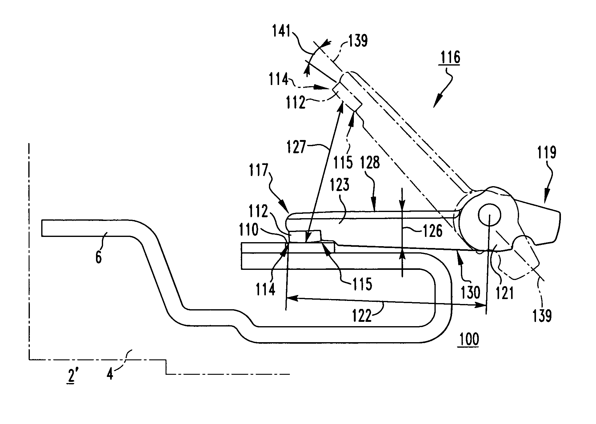
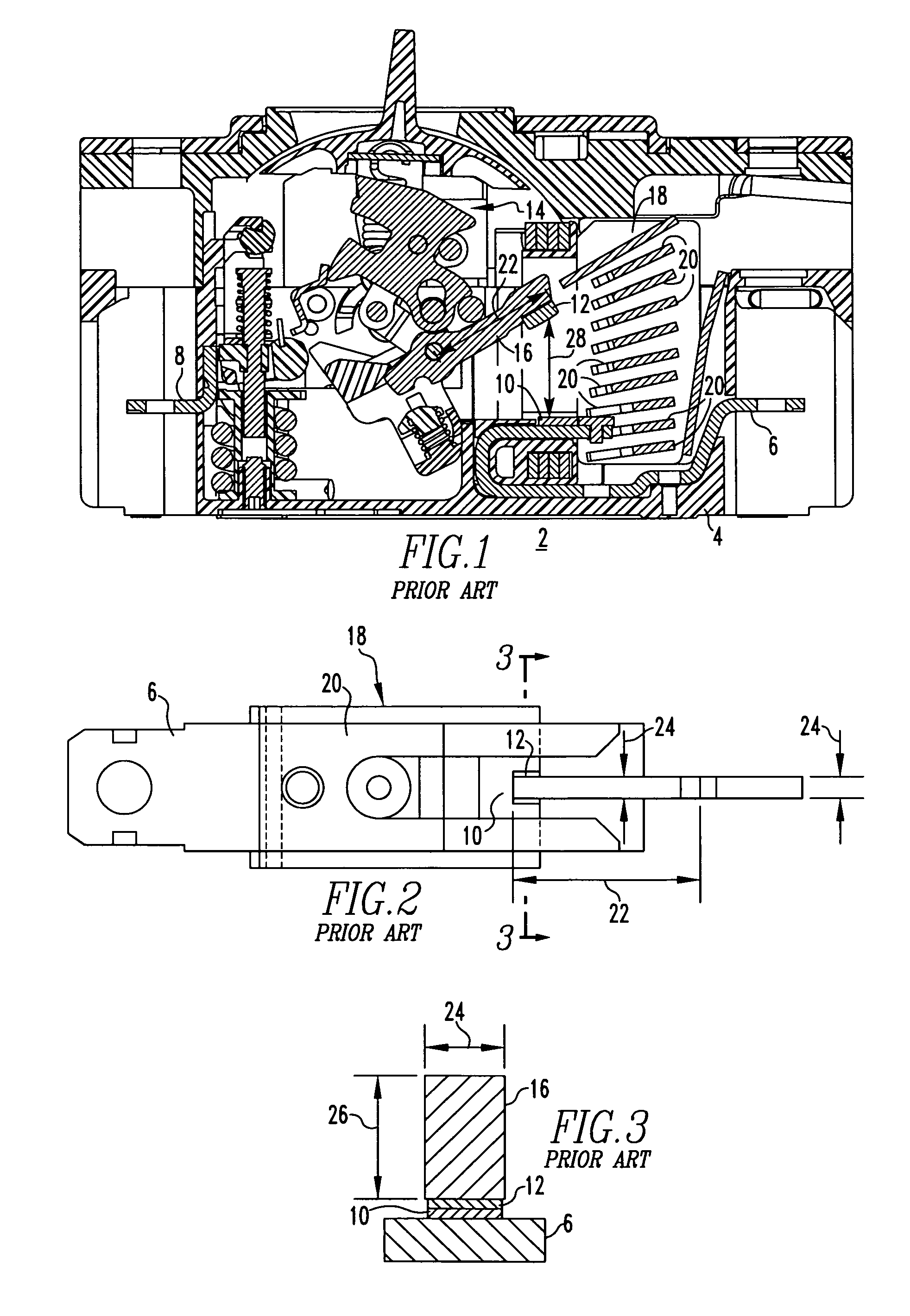
[0042]FIGS. 4, 5, and 6 show a contact assembly 100 including a movable contact arm 116 as employed in a molded case circuit breaker (MCCB) 2, partially shown in FIG. 4. It will be appreciated that, except for the contact assembly 100, which will now be discussed, the MCCB 2′, (FIG. 4) is, otherwise, substantially identical to the MCCB 2 shown and previously described with respect to FIG. 1.

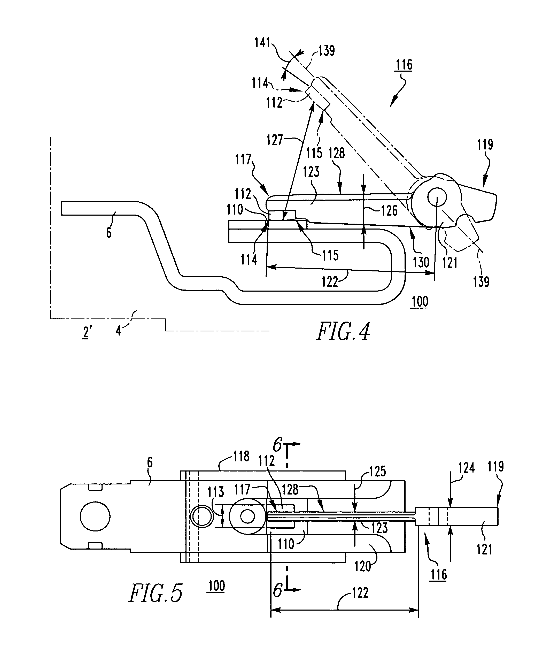
[0043]The contact assembly 100 includes a fixed contact 110 which is coupled to the folded back line conductor 6 housed within the housing 4 (FIG. 4) of the MCCB 2′ (FIG. 4), and a movable contact 112 which is mounted on the movable contact arm 116. Electrical connection of the movable contact arm 116 to the load conductor 8 (not shown) (see, for example, FIG. 1) of the MCCB 2′ is provided in the same manner as movable contact arm 16 of FIG. 1. The movable contact arm 116 has a first end structured to carry the movable contact 112, a second end 119 disposed distal from the first end 117, a pivot ...

example 2

[0051]As a non-limiting example, the moving arm portion 123 of the movable contact arm 116 of FIGS. 4–6 has a length 122 of about 1.168 inches, a second width 125 of about 0.062 inches, and a height 126 of about 0.250 inches.

example 3

[0052]FIGS. 7A and 7B show cross-sectional and top plan views, respectively, of a contact assembly 200 having a movable contact arm 216 substantially similar to movable contact arm 116 previously discussed in connection with FIGS. 4–6, but having a pivot portion 221 which comprises a number of spacers 236,238. Specifically, the example pivot portion 221 includes a pair of spacers 236,238 disposed on opposite sides of the moving arm portion 223 of the movable contact arm 216 proximate the second end 219 of the movable contact arm. Each of the spacers 236,238 has a width 240, wherein the first width 224 of the pivot portion 221 of the movable contact arm 216 includes the combined width 240 of all of the spacers (e.g., spacers 236,238), along with the second width 225 of the moving arm portion 223.

[0053]The pivot portion 221 pivotably couples the movable contact arm 216 to the crossbar 203 (shown in simplified form in FIG. 7B) of the circuit breaker operating mechanism 14 (FIG. 1). As ...


PUM


Abstract

A contact assembly for a circuit breaker includes a fixed contact, a movable contact, and a movable contact arm. The movable contact arm includes a first end carrying the movable contact, a second end, and a pivot portion proximate the second end. A moving arm portion extends from the first end toward the pivot portion. The moving arm portion has a width, an upper edge, a lower edge, and a height defined by the distance between the upper edge and the lower edge. In response to a trip condition, the movable contact separates from the fixed contact and the movable contact arm pivots open at an angular opening velocity. The height of the moving arm portion of the movable contact arm is at least four times the width of the moving arm portion, thus minimizing the moment-of-inertia of the movable contact arm, and increasing the angular opening velocity.

Description

BACKGROUND OF THE INVENTION[0001]1. Field of the Invention[0002]The invention relates generally to electrical switching apparatus and, more particularly, to contact assemblies for electrical switching apparatus, such as circuit breakers. The invention also relates to movable contact arms for circuit breaker contact assemblies.[0003]2. Background Information[0004]Electrical switching apparatus, such as circuit breakers, are employed in diverse capacities in power distribution systems such as, for example, to provide protection for electrical equipment from electrical fault conditions (e.g., without limitation, current overloads; short circuits; abnormal level voltage conditions).[0005]As shown in FIGS. 1 and 2, a circuit breaker 2 (FIG. 1) generally includes a housing 4 which encloses a line conductor 6, a load conductor 8 (FIG. 1), a fixed contact 10 and a movable contact 12, with the movable contact 12 being movable into and out of electrical contact with the fixed contact 10. This...

Claims


Application Information

Patent Timeline
IPC IPC(8): H01H1/22
CPCH01H1/22H01H73/04
Inventor SHEA, JOHN J.MILLER, JEFFREY A.SCHALTENBRAND, BRIAN J.
Owner EATON INTELLIGENT POWER LIMITED
Why Eureka
Try Eureka