OTDR with increased precision and reduced dead zone using superposition of pulses with varying clock signal delay

a clock signal delay and superposition technology, applied in the field of fiberoptic communication, can solve the problems of a large amount of light to be reflected back, achieve the effects of reducing the uncertainty of position determination, avoiding jitter and wander, and improving accuracy

Active Publication Date: 2022-03-29
XIEON NETWORKS SARL
View PDF15 Cites 0 Cited by
  • Summary
  • Abstract
  • Description
  • Claims
  • Application Information

AI Technical Summary

Benefits of technology

[0017]Consequently, the position of the irregularity in the optical transmission fiber can be determined with precision even using relatively long sampling light pulses with relative low peak powers and a receiver with relatively low time resolution. A higher precision is mainly required in the analysis of the combined signal. Thus, advantageously, the accuracy for determining the position of the irregularity in the optical transmission fiber does not directly depend on the sampling period or the pulse width. Thereby, high resolution in the detection of the position of the irregularity can be achieved without necessarily resorting to costly and technically involved high-speed hardware. Further, since the position of the irregularity is determined from the combined signal, not by the individual detection signals, the longer lengths of the pulses—as compared to conventional methods for determining the position of an irregularity in an optical transmission system—do not result in a longer dead zone.
[0038]In preferred embodiments of the invention, for each of the different delays, a predetermined number of sampling light pulses is emitted, a predetermined number of detection signals with a same delay is generated, and an average detection signal is generated by averaging over the predetermined number of detection signals for each of the different delays, and wherein the combined signal corresponds to a superposition of the average detection signals. For example, K different sampling light pulses might be emitted and consequently K different detection signals with a given delay may be generated. The average detection signal for the given delay then results from averaging over the K detection signals corresponding to the given delay. The combined signal then corresponds to a superposition of the average detection signals. This averaging mechanism generates a cleaner combined signal which is less subject to random error sources. The same effect can be achieved by first generating several combination signals and finally averaging over the several combination signals.

Problems solved by technology

When a sampling light pulse reaches the irregularity, the abrupt change in the index of refraction with respect to that of the optical transmission fiber causes a considerable amount of light to be reflected back due to Fresnel reflection.

Method used


Image

  • OTDR with increased precision and reduced dead zone using superposition of pulses with varying clock signal delay
  • OTDR with increased precision and reduced dead zone using superposition of pulses with varying clock signal delay
  • OTDR with increased precision and reduced dead zone using superposition of pulses with varying clock signal delay

Examples


Embodiment Construction

[0075]For the purposes of promoting an understanding of the principles of the invention, reference will now be made to a preferred embodiment illustrated in the drawings, and specific language will be used to describe the same. It will nevertheless be understood that no limitation of the scope of the invention is thereby intended, such alterations and further modifications in the illustrated apparatus and such further applications of the principles of the invention as illustrated therein being contemplated as would normally occur now or in the future to one skilled in the art to which the invention relates.

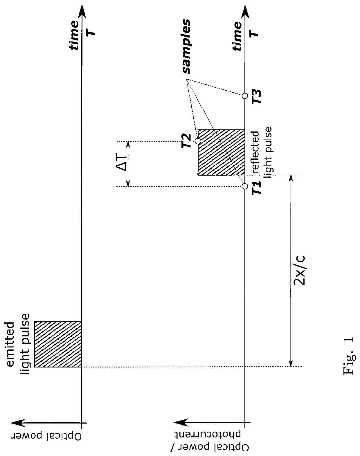
[0076]FIG. 1 shows a schematic representation of a conventional method for determining the position of an irregularity in an optical transmission fiber using an OTDR commonly known in the art. The figure shows in the upper row the time evolution of a light pulse emitted by the OTDR and in the lower row the reflected light pulse resulting from the reflection at a distance x from th...


PUM

PropertyMeasurementUnit
timeaaaaaaaaaa
timeaaaaaaaaaa
timeaaaaaaaaaa

Abstract

A method for determining the position of an irregularity in an optical transmission fiber using an optical time domain reflectometer, the method comprising the steps of emitting a succession of sampling light pulses into the optical transmission fiber, detecting reflected light pulses resulting from the reflection of the sampling light pulses at the irregularity in the optical transmission fiber and generating corresponding time-dependent detection signals, wherein different delays are associated with detection signals corresponding to different sampling light pulses, obtaining a combined signal from the detection signals, and analyzing the combined signal for determining the position of the irregularity in the optical transmission fiber with respect to the optical time domain reflectometer, wherein the combined signal corresponds to a superposition of the detection signals.

Description

RELATED APPLICATIONS[0001]This application is a 35 U.S.C. 371 national stage filing of International Application No. PCT / EP2017 / 062551, filed on May 24, 2017, which claims priority to European Patent Application No. 16171796.2, filed on May 27, 2016. The entire contents of these applications are incorporated herein by reference in their entirety.FIELD OF THE INVENTION[0002]The present invention is in the field of fiber-optic communication. In particular, the present invention relates to a method for determining the position of an irregularity in an optical transmission fiber using an optical time domain reflectometer (OTDR) and a correspondingly configured OTDR for determining the position of an irregularity in an optical transmission fiber.BACKGROUND OF THE INVENTION[0003]OTDRs are used in the field of fiber-optic communication to gain insight into the main optical parameters of an optical transmission fiber, like information regarding fiber attenuation, and to detect impairments o...

Claims


Application Information

Patent Timeline
Patent Type & Authority Patents(United States)
IPC IPC(8): G01M11/00
CPCG01M11/3118G01M11/3145
Inventor RAPP, LUTZDUARTE PEREIRA, NUNO RENATO
Owner XIEON NETWORKS SARL
Why Eureka
Try Eureka