Beam generation optical system and image capturing apparatus provided with the same
a technology of beam generation and optical system, which is applied in the field of beam generation optical system, can solve the problems of reduced separation degree, limited light source size, and thin optical system
- Summary
- Abstract
- Description
- Claims
- Application Information
AI Technical Summary
Benefits of technology
Problems solved by technology
Method used
Image

Examples
first embodiment
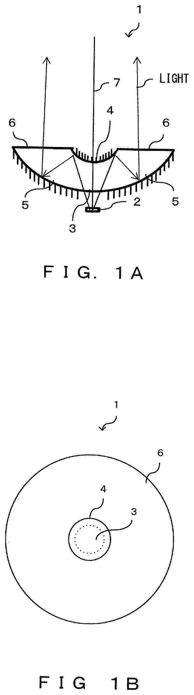
[0057]The following describes a first embodiment by referring to drawings. The present invention features optical elements, and non-optical-element components of an image capturing apparatus of the invention that includes a beam generation optical system are similar to those seen in the prior art. Accordingly, descriptions of such non-optical-element components are omitted herein. This is also applicable to the other embodiments described hereinafter. The image capturing apparatus of the present invention, i.e., an image capturing apparatus that includes a beam generation optical system, does not need to be provided with an aperture, i.e., a component of the conventional image capturing apparatus.
[0058]FIGS. 1A and 1B each depict the appearance of an optical element in accordance with the first embodiment. FIG. 1A is a side view of an optical element 1 as seen from the side. FIG. 1B is a plane view of the optical element 1 as seen from above. As with the conventional spherical lens,...
second embodiment
[0066]The following describes a second embodiment by referring to drawings. FIGS. 3A and 3B each depict the appearance of an optical element in accordance with the second embodiment. FIG. 3A is a side view of an optical element 21 as seen from the side. FIG. 3B is a plane view of the optical element 21 as seen from above. As with the optical element 1 in accordance with the first embodiment, the optical element 21 depicted in FIGS. 3A and 3B receives light emitted from a light source (LED) 2.
[0067]While the optical element 1 of the first embodiment includes a base having a downward convex shape, the optical element 21 of the second embodiment includes a base having convex shapes on both sides, as depicted in FIG. 3A. In particular, a second reflection section 25 forms a convex shape on the light-source-2 side, and a second transmissive section 26 forms a convex shape on an opposite side from the light-source-2 side.
[0068]The optical element 21 includes, at a center of a light-incide...
third embodiment
[0076]The following describes a third embodiment by referring to drawings. In the embodiments described above, the optical element includes a base having a downward convex shape (a planer shape and a convex shape on the upper side) or a base having convex shapes on both sides, and metal is deposited on portions of the optical element so that these portions can function as reflective surfaces. In the third embodiment and a fourth embodiment described hereinafter, optical elements different from those described above are used in consideration of manufacturability and costs.
[0077]FIGS. 8A and 8B each depict the appearance of an optical element in accordance with the third embodiment. FIG. 8A is a perspective view of an optical element 31 as seen obliquely from above. FIG. 8B is a side view of the optical element 31 as seen from the side. As with the optical element 21 in accordance with the second embodiment, the optical element 31 depicted in FIGS. 8A and 8B receives light emitted fro...
PUM
| Property | Measurement | Unit |
|---|---|---|
| distance | aaaaa | aaaaa |
| distance | aaaaa | aaaaa |
| distance | aaaaa | aaaaa |
Abstract
Description
Claims
Application Information
 - R&D Engineer
- R&D Manager
- IP Professional
- Industry Leading Data Capabilities
- Powerful AI technology
- Patent DNA Extraction
Browse by: Latest US Patents, China's latest patents, Technical Efficacy Thesaurus, Application Domain, Technology Topic.
© 2024 PatSnap. All rights reserved.Legal|Privacy policy|Modern Slavery Act Transparency Statement|Sitemap