Rod lens array and equal-magnification imaging optical apparatus using rod lens array

a technology of equal-magnification imaging and lens array, which is applied in the direction of lenses, optical elements, instruments, etc., can solve the problems of assembly errors and insufficient suppression of light quantity unevenness, and achieve the effect of reducing light quantity unevenness

Active Publication Date: 2015-08-11
MITSUBISHI CHEM CORP
View PDF10 Cites 1 Cited by
  • Summary
  • Abstract
  • Description
  • Claims
  • Application Information

AI Technical Summary

Benefits of technology

[0010]The present invention is to provide a rod lens array capable of minimizing light quantity unevenness even in the case where assembly error or aged deterioration occurs and an equal-magnification imaging optical apparatus using such a rod lens array.
[0011]According to experiments executed by the inventors of the present invention, it has been found that, by setting the overlap degree m of the rod lens to be 2.55 or more and 4 or less and setting the aperture angle of the rod lens represented by n0·g·r0 to be 0.1 or more and less than 0.22, it is possible to suppress the light quantity unevenness and to increase the resolution by increasing the overlap degree.
[0014]In the related art, there is a problem in that, if the overlap degree m exceeds 2.5, the brightness of image is decreased, and thus, the resolution is decreased. However, in the rod lens array according to the present invention, by designing the aperture angle relatively as small as 0.1 or more and less than 0.22, light is condensed so that it is possible to suppress darkening of an image. Furthermore, it can be understood that the overlap degree is set to be 2.55 or more and 4 or less by using the rod lens having the above-described aperture angle, so that it is possible to provide a rod lens array having very small light quantity unevenness and high resolution.
[0017]In the rod lens array according to the present invention, since the aperture angle is relatively small and the radius of field of view is small, it is preferable that the lens length Z0 and the operation distance L0 be set to be long in order to increase the overlap degree m. By setting the values to be in the above-described range, it is possible to easily perform optical design of a rod lens having small light quantity unevenness and high resolution.
[0022]According to the present invention having the above-described configuration, even in the case where assembly error or aged deterioration occurs, it is possible to minimize the light quantity unevenness.

Problems solved by technology

However, although the overlap degree is set in the range disclosed in Japanese Patent Laid-Open No. 11-64605, the light quantity unevenness may not be sufficiently suppressed.
Particularly, when an optical apparatus such as a facsimile, a copier, a printer, and a scanner is to be assembled, assembly error occurs between a surface of a document and an end surface of a rod lens array or between a surface of a sensor and the end surface of the rod lens array.

Method used


Image

  • Rod lens array and equal-magnification imaging optical apparatus using rod lens array
  • Rod lens array and equal-magnification imaging optical apparatus using rod lens array

Examples


examples

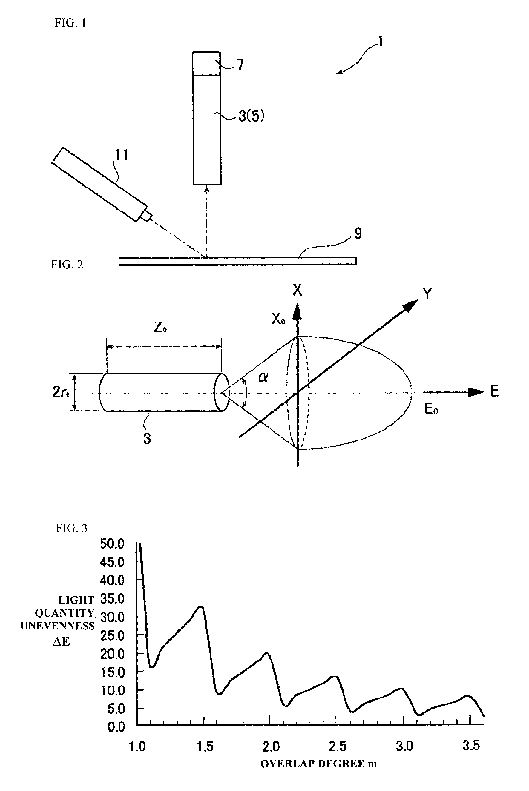
[0052]Hereinafter, Examples and Comparative Examples of the present invention will be described in detail. In the specification, in Examples and Comparative Examples, rod lenses listed in Table 1 were used, and the value of overlap degree m was allowed to be changed.

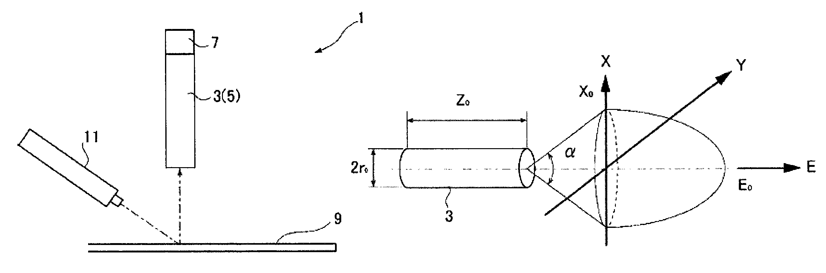
[0053]In Examples and Comparative Examples, values of the refractive index n0 on the optical axis (at the center of the rod lens), the effective radius r0, the gradient index constant g, the aperture angle n0·g·r0, the lens length Z0, the lens pitch 2R, the operation distance L0, and the radius of field of view X0 are listed in Table 1. In addition, in Examples 1 to 3, by cutting a rod lens array RA84T-P11 (Z0=4.4 mm) in a longitudinal direction of the lenses manufactured by Mitsubishi Rayon Co., Ltd., Z0=4.13 (Example 1), Z0=4.07 (Example 2), and Z0=4.03 (Example 3) were obtained. In addition, the overlap degree was obtained by the above-described Mathematical Formula 5. In addition, after disposing a diffusion plate on...


PUM

PropertyMeasurementUnit
length Z0aaaaaaaaaa
glass transition temperature Tgaaaaaaaaaa
refractive indexaaaaaaaaaa

Abstract

A rod lens array is configured so that when a relation between R and r0 is set to be R≧r0≧0.8R, and the gradient index of the rod lens is approximate to n(r)2=n02{1−(g·r)2}, an overlap degree m, defined by m=X0 / 2R, is 2.55 or more and 4 or less and an aperture angle of the rod lens, represented by n0·g·r0, is 0.1 or more and less than 0.22. The array is capable of minimizing light quantity unevenness even where there may be assembly error or aged deterioration occurs. An equal-magnification imaging optical apparatus usefully includes a rod lens array.

Description

CROSS-REFERENCE TO RELATED APPLICATIONS[0001]This U.S. application claims priority from Japanese Patent Application 2012-278211, filed Dec. 20, 2012, the complete disclosure of which is hereby incorporated herein by reference in their entirety for all purposes.BACKGROUND OF THE INVENTION[0002]1. Field of the Invention[0003]The present invention relates to a rod lens array and an equal-magnification imaging optical apparatus using a rod lens array, and more particularly, to a rod lens array used for reading an image in an image reading apparatus and an equal-magnification imaging optical apparatus using a rod lens array.[0004]2. Description of the Related Art[0005]In the related art, in an image reading apparatus such as a scanner or a facsimile, a technique of allowing light emitted from a light source to irradiate a document and allowing a CCD sensor to receive the reflected light through a rod lens array is widely used.[0006]In recent years, it is desired to improve a document rea...

Claims


Application Information

Patent Timeline
Patent Type & Authority Patents(United States)
IPC IPC(8): G02B27/10G02B1/04G02B3/00H04N1/031G02B7/02
CPCG02B1/041G02B3/0006G02B3/0087H04N1/0312C08L33/10
Inventor IIMORI, MASASHIINUZUKA, SHINGO
Owner MITSUBISHI CHEM CORP
Why Eureka
Try Eureka