
Check valve assembly

a technology of valve assembly and valve disk, which is applied in the direction of machines/engines, liquid fuel engines, and positive displacement liquid engines, etc., can solve the problems of complex structure necessary for mounting the valve disk on the valve body, the risk of breaking during the functioning of the valve, and the manufacturing and maintenance costs afferent to such a valve, so as to achieve a strong and reliable connection

Active Publication Date: 2022-04-05
ATLAS COPCO AIRPOWER NV
View PDF38 Cites 2 Cited by
  • Summary
  • Abstract
  • Description
  • Claims
  • Application Information

AI Technical Summary

Benefits of technology

This patent introduces a new valve design that is long-lasting, easy to assemble, and low maintenance. The valve has a simple design, and it allows the motor to require less power for starting the compressor or vacuum pump, resulting in higher efficiency and reduced energy and maintenance costs.

Problems solved by technology

One drawback of the valve disclosed in the above identified patent document is the complex structure necessary for mounting the valve disk on the valve body.
Another drawback is the risk of breakage during the functioning of said valve due to the improper reinforcement of the shaft along its length.
Other drawbacks consist of the manufacturing and maintenance costs afferent to such a valve due to the numerous complex and non-standard components used throughout its layout.
One of the drawbacks of such a valve is the complex design, because of which the manufacturing and maintenance processes become burdensome and costly.
A further drawback is the risk of experiencing breakages at the level of the connection between the turning plate and the housing due to an improper support of the rotary shaft.

Method used


Image

  • Check valve assembly
  • Check valve assembly
  • Check valve assembly

Examples


Embodiment Construction

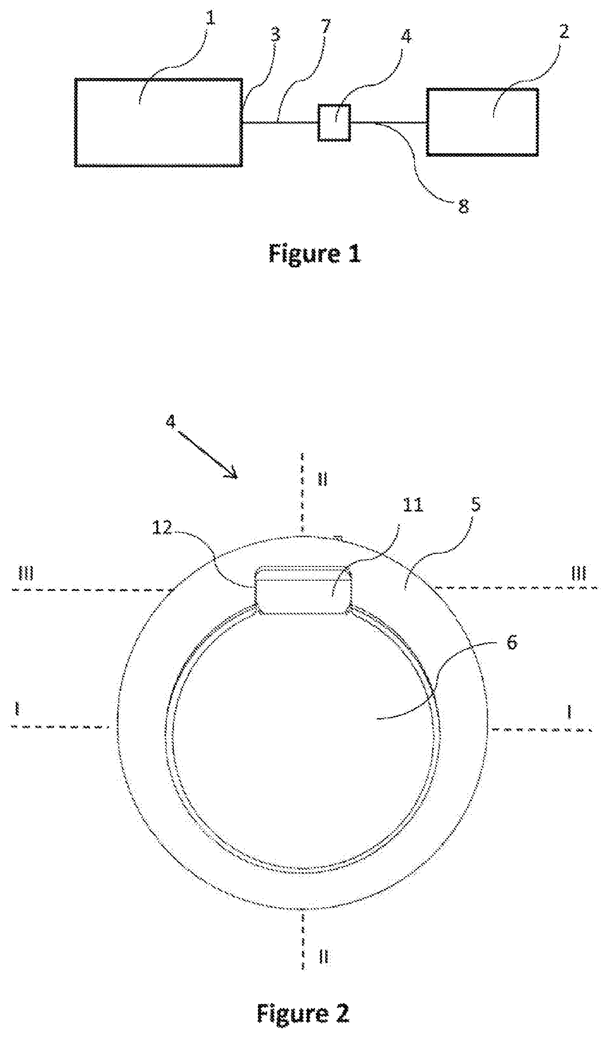
[0052]FIG. 1 illustrates a compressed air system whereby a compressor unit 1 provides compressed air to an external network 2. The flow of fluid at a discharge port 3 of the compressor unit 1 is controlled by means of check valve assembly 4.

[0053]Similarly, FIG. 11 illustrates a vacuum pump system whereby a vacuum pump 100 provides vacuum to an external network 2. The flow of fluid at the intake port 300 of the vacuum pump 100 is controlled by means of check valve assembly 4.

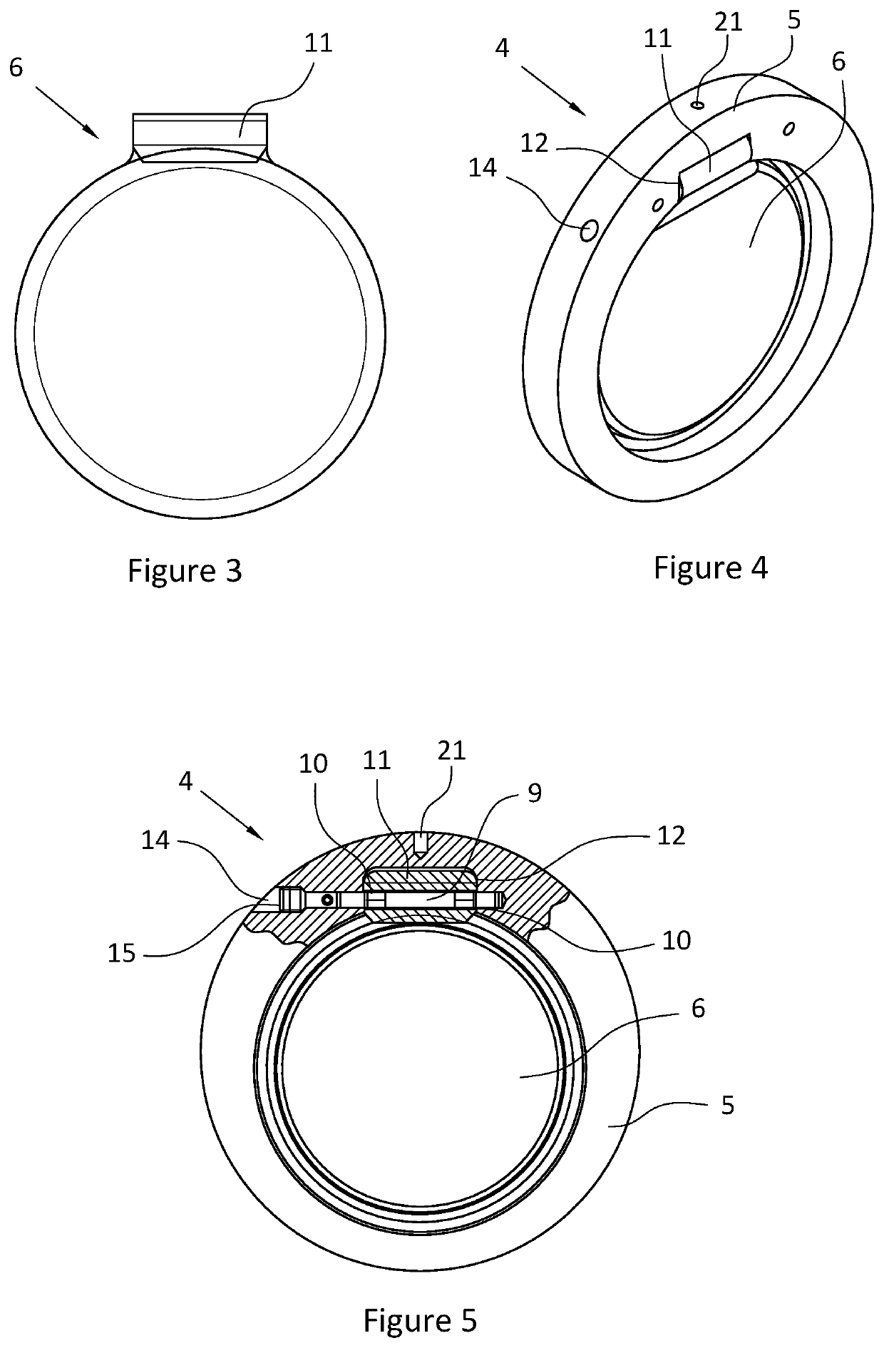
[0054]The check valve assembly 4 comprises a valve body 5 receiving a valve plate 6, as illustrated at least in FIG. 2.

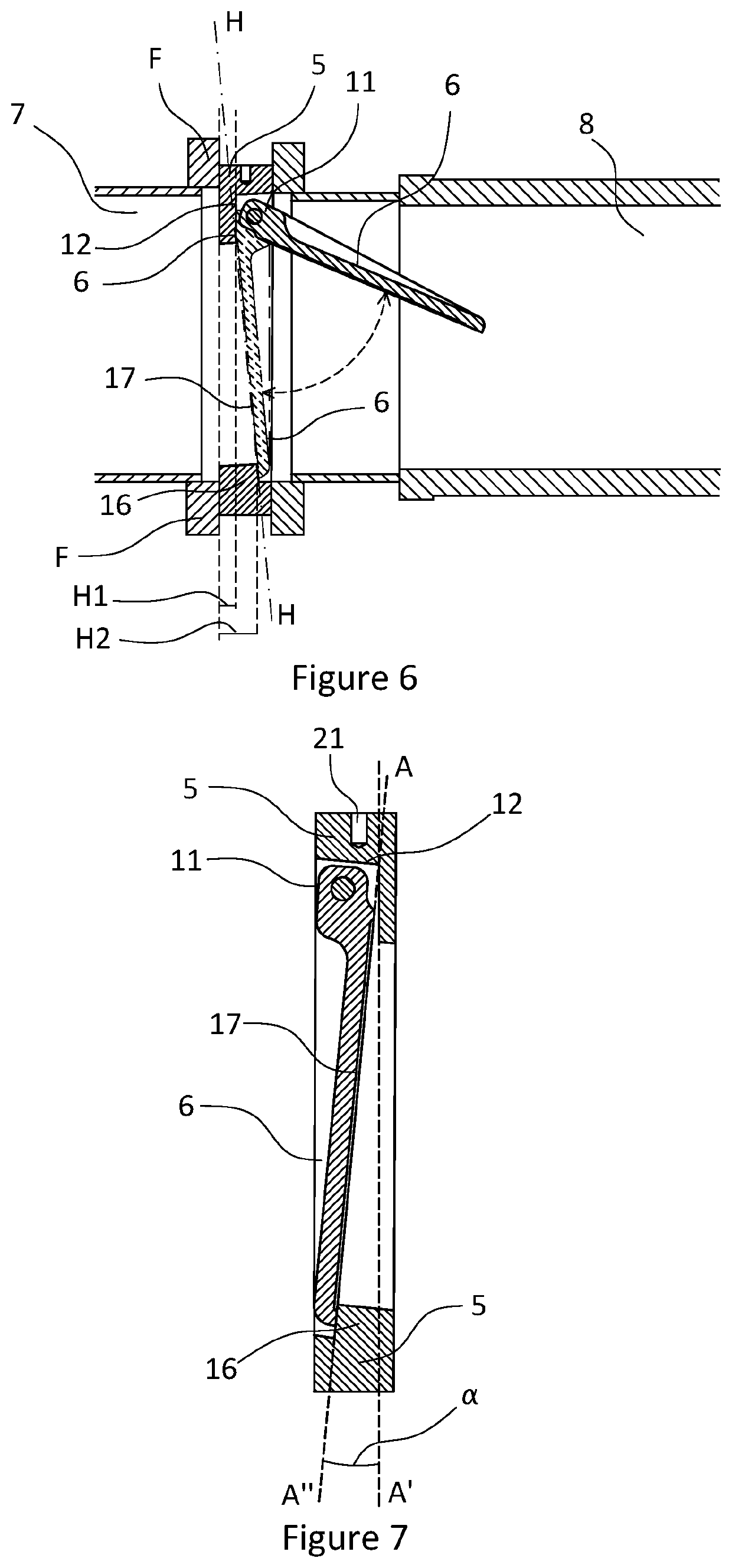
[0055]The valve plate 6 is being adapted to pivot between a first open position in which fluid can flow through said check valve 4 and a second closed position in which fluid cannot flow through said check valve 4, as illustrated in FIG. 6 and FIG. 12.

[0056]In the case of a compressor unit 1, the valve body 5 is preferably mounted to a discharge port 3 of said compressor unit 1 through a first f...


PUM


Abstract

A check valve assembly for a compressor or a vacuum pump includes a valve body adapted to receive a valve plate pivoting between a first open position and a second closed position. The valve body is connected to a discharge port of a compressor unit or to the intake port of a vacuum pump. A second fluid conduit is attachable to the valve body and is connected to an external network. The assembly includes a shaft and at least one bearing for connecting the valve plate to the valve body. The valve plate includes an elongated area having a hollow tube through which the shaft is inserted for rotatably mounting the valve plate. At least one bearing is positioned on the shaft within the hollow tube.

Description

BACKGROUND OF THE INVENTION[0001]This invention relates to a check valve assembly configured to be mounted at the interface between a compressor unit or a vacuum pump and an external network, for preventing a fluid flow in the upstream direction, the check valve assembly comprising: a valve body adapted to receive a valve plate, said valve plate being adapted to pivot between a first open position in which fluid can flow through said check valve and a second closed position in which fluid cannot flow through said check valve; said valve body being adapted to be connected to a discharge port of a compressor unit or to the intake port of a vacuum pump through a first fluid conduit; a second fluid conduit attachable to the valve body, said second fluid conduit being adapted to be connected to an external network; a shaft and at least one bearing for connecting the valve plate to the valve body.[0002]Check valves for controlling the flow of fluid on a fluid conduit are currently used.[0...

Claims


Application Information

Patent Timeline
Patent Type & Authority Patents(United States)
IPC IPC(8): F16K15/03F04B39/10F04B53/10F04C25/02F04C29/12
CPCF16K15/03F04B39/10F04B53/104F04C25/02F04C29/126Y10T137/7898F04B39/1066F04B39/102
Inventor CLAES, ERWIN LOUIS ANNIE
Owner ATLAS COPCO AIRPOWER NV
Learn More