Screw-attached pick-up dental coping system and methods

a coping system and screw-attached technology, applied in the field of screw-attached pick-up dental coping system and methods, can solve the problems of reducing the mechanical stability of the existing denture, affecting the comfort of patients, and complicating the installation process

Active Publication Date: 2022-04-26
SMART DENTURE CONVERSIONS LLC
View PDF104 Cites 0 Cited by
  • Summary
  • Abstract
  • Description
  • Claims
  • Application Information

AI Technical Summary

Benefits of technology

[0015]Some embodiments of the invention include a screw-in fastener system used to temporarily retain a coping on an abutment during bonding of the coping into a blind hole located in the tissue-side of a removable dental element such as a removable complete denture. The temporary fastener system disclosed has features to allow easy removal of the dental prosthesis from the fastener post after pick-up of the coping into the dental prosthesis is complete, without the need for special tools or access to the fastener system to unscrew it.
[0016]Some embodiments include a temporary fastener with a male-threaded bottom portion that is installed into the screw threads of an abutment, and an axially separable top portion, or cap, that retains the coping onto the abutment. The separable portion allows removal of the coping picked-up in the dental prosthesis without requiring mechanical access to the fastener. The inventive concepts disclosed facilitate easier installation and removal on multiple abutments that may be oriented at different compound angles when compared to the conventional open-tray processes and long impression screws. The temporary fastener may engage the same screw threads of the abutment that are used to definitively attach the prosthesis. In this manner, the coping is held against the abutment for the pick-up process with a force oriented identically to that of the final screw mounting. The retention of the cap on the screw post can be designed to provide a desired force holding the coping to the abutment through the applied torque on the temporary fastener. The cap can be attached to the post through a combination of known mechanical attachment means including but not limited to interference fits, adhesives, snap fits or other elastic and inelastically deforming retention elements. The cap may also be formed as an integral part of the screw post that has portions that fracture as a result of an applied axial force. In addition to applied axial forces, the cap may separate from the post as a result of retention changes resulting from chemical or thermal processes and or the application of electromagnetic energy during or subsequent to the pick-up process.

Problems solved by technology

Transfer copings introduce an indirect secondary alignment reference since the insertion of the coping into the impression may not accurately duplicate the original position, particularly in insertion depth.
Some snap-on systems provide features to provide different retention levels, but this complicates the installation process.
Special tools have been introduced to help separate impression trays or prostheses with snap-on systems, but may still result in patient discomfort.
Since snap-on systems are generally physically larger than dental screws, converting an existing denture may require large clearance cavities to be bored into the existing denture before it can be used as an impression tray in a pick-up coping process.
These large holes may significantly reduce the mechanical stability of the existing denture.
The mechanical precision required of snap-on system elements generally makes them more expensive than screw-attached systems.
A disadvantage with commercially available screw-attachment systems for pick-up copings is the requirement for using an open-tray impression in order to release the coping from the abutment after the impression material sets.
The copings used with the impression screws are often relatively long and require modification for denture conversion.
This customization may result in larger clearance holes in dentures and require additional process time by the dental practitioner.
The length of the impression screws sticking through the tray can cause patient discomfort and a gag reflex.
In the case of denture conversion, clearance for a set of impression screws at different angles may require additional material removal leading to a weakened denture.
The disadvantage of the 3-D printed model for full arch implant prosthetics is the positioning of the implant lab analog within the 3-D printed model introduces a degree of inaccuracy.
Additionally, an impression only captures the implant or multi-unit abutment relative to the tissues and requires cumbersome steps to incorporate a provisional prosthesis or wax-up into the design software relative to the scan of the impression.
However, if the mechanical integrity of the converted denture is compromised, the scanned information may not faithfully represent the relative geometry of these elements and result in a poor fit.
Other alignment systems have been proposed which use silicone or melting screw threads to allow closed tray transfer for definitive screw attachment, but the practicality of providing adequate alignment and seating forces with a screw diameter in the range of existing systems or overcoming the lack of disengagement independence required in melting all threads simultaneously without patient discomfort has not been documented.

Method used


Image

  • Screw-attached pick-up dental coping system and methods
  • Screw-attached pick-up dental coping system and methods
  • Screw-attached pick-up dental coping system and methods

Examples


Embodiment Construction

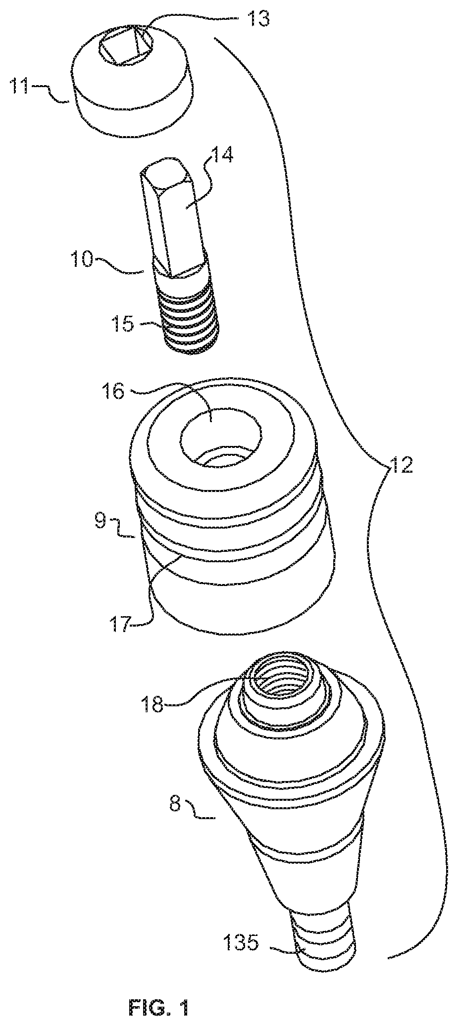
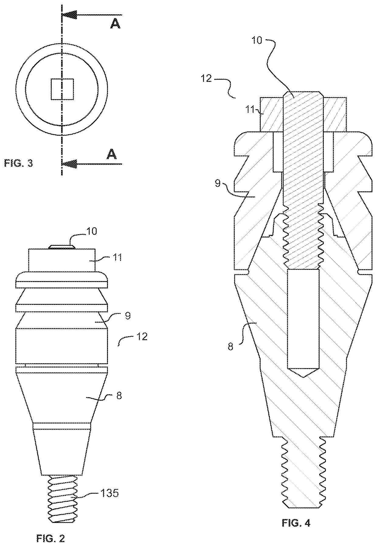
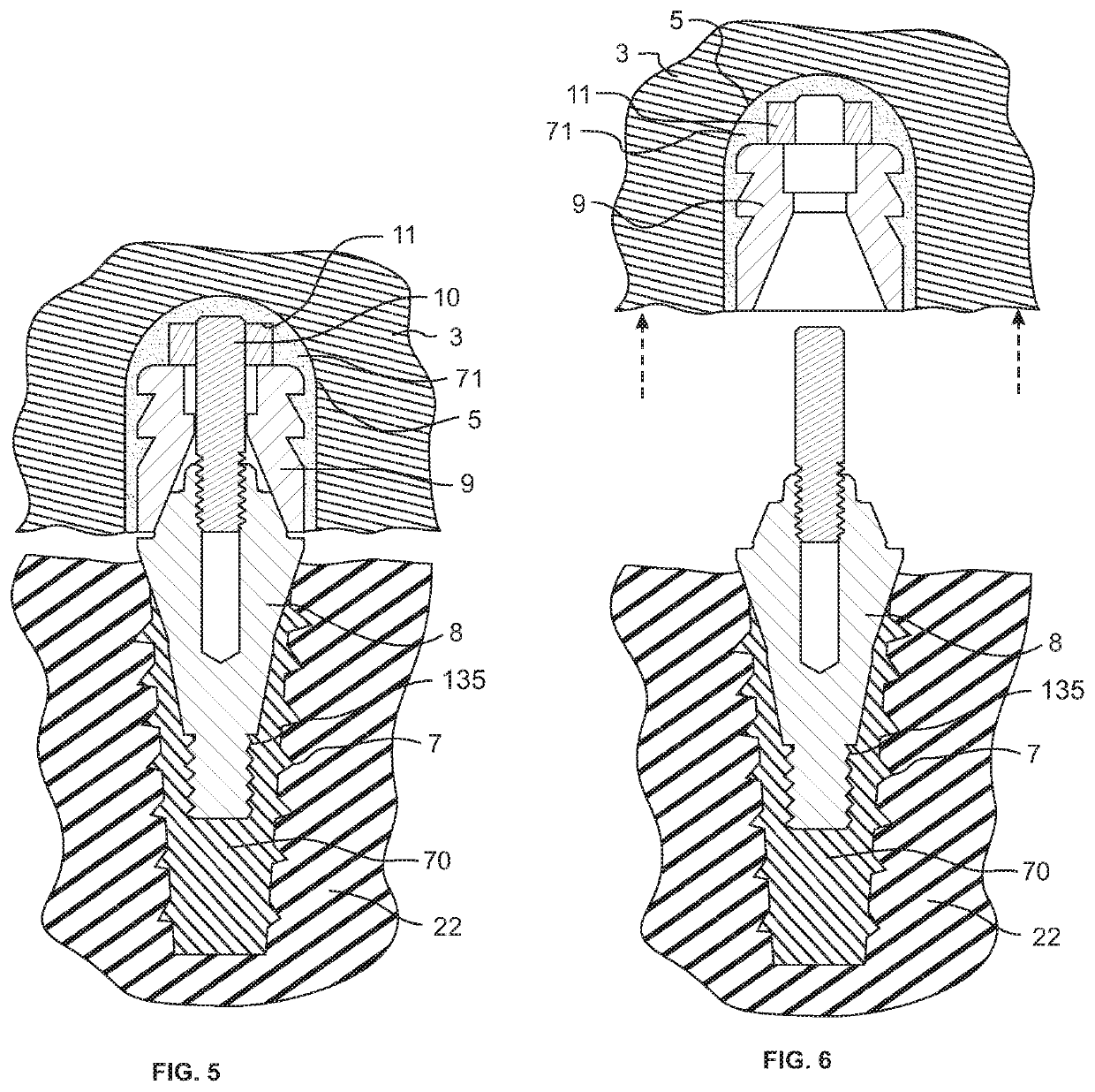
[0136]FIG. 1 shows an exploded view of one embodiment of a temporary alignment system 12 for use in a direct coping pick-up process for screw attachment of a prosthesis. Implant abutment 8 has a distal end which may include attachment feature portion 135 illustrated as a screw thread for direct attachment to the patient's jaw and a proximal end with an abutment shaped to accommodate a coping 9. The abutment includes threaded section 18. The coping has a central bore 16 to accommodate screw fastening and may include ridges 17 or other structures or surface treatments to increase retention to the prosthesis with adhesive. The coping and abutment mating surfaces as shown in FIG. 1 are symmetrical. The inventive concepts of this disclosure may also be applied to abutment and coping systems that are keyed to restrict mating orientation. The coping may be mounted onto the abutment through rotation of a temporary adjustment screw comprising a threaded post 10 and cap 11. The cap 11 is mech...


PUM


Abstract

A temporary alignment system and method for holding a dental coping to an implant abutment using the same threads in the abutment that are used for definitive attachment are disclosed. The disclosed temporary fasteners initially orient and hold a coping against an abutment with a force along the same axis as the semi-definitive screw. The aligned coping can be picked-up in a closed-tray impression process without unscrewing the temporary fastener. Embodiments include threaded posts that release copings from the abutment through axial forces. Some embodiments include a threaded post with separable cap that is picked-up with the coping. Methods for converting an existing prosthesis for screw attachment to implants in a single visit and digital capture of the converted prosthesis are described.

Description

CROSS-REFERENCE TO RELATED APPLICATIONS[0001]This disclosure claims priority of U.S. provisional patent application No. 62 / 742,942, filed on Oct. 9, 2018, and U.S. provisional patent application No. 62 / 774,402, filed on Dec. 3, 2018, and U.S. provisional patent application No. 62 / 818,082, filed on Mar. 13, 2019. All of the above provisional applications are incorporated herein by reference in their entirety.COPYRIGHT NOTICE[0002]A portion of the disclosure of this patent application contains material that is subject to copyright protection. The copyright owner has no objection to the reproduction by anyone of the patent document or the patent disclosure as it appears in the Patent and Trademark Office patent files or records, but otherwise reserves all copyright rights whatsoever.BACKGROUND OF THE INVENTION[0003]Different systems have been introduced for attaching dental prostheses to dental implants to replace one or more natural teeth. In order to simplify future modification or r...

Claims


Application Information

Patent Timeline
Patent Type & Authority Patents(United States)
IPC IPC(8): A61C8/00
CPCA61C8/0068A61C8/0066A61C8/0074A61C8/0078A61C2008/0084A61C8/0001A61C13/34A61C9/0053A61C9/0093A61C8/0089A61C1/186A61C8/0095A61C2201/00
Inventor KOFFORD, BRANDON DALERUDISILL, CHARLES ALBERT
Owner SMART DENTURE CONVERSIONS LLC
Why Eureka
Try Eureka