
Optical demultiplexer with truncated profile and an optical transceiver module implementing same

a technology of optical transceiver and profile, applied in the field of optical demultiplexers, can solve the problems of significant design and manufacturing challenges of scaling

Active Publication Date: 2022-05-03
USAA
View PDF18 Cites 2 Cited by
  • Summary
  • Abstract
  • Description
  • Claims
  • Application Information

AI Technical Summary

Benefits of technology

The present patent is about a device called an optical demultiplexer that is used in an optical subassembly. The demultiplexer has a body with a truncated profile that reduces its size. The device has a plurality of waveguides that separate channel wavelengths from a multiplexed optical signal. The output of the device emits separated channel wavelengths. The technical effect of the patent is to provide a compact and efficient solution for separating optical signals in optical subassemblies.

Problems solved by technology

The desire to provide higher transmit / receive speeds in increasingly space-constrained optical transceiver modules has presented challenges, for example, with respect to thermal management, insertion loss, RF driving signal quality and manufacturing yield.
Transceiver modules continue to scale to meet market demand, but such scaling raises significant design and manufacturing challenges.

Method used


Image

  • Optical demultiplexer with truncated profile and an optical transceiver module implementing same
  • Optical demultiplexer with truncated profile and an optical transceiver module implementing same
  • Optical demultiplexer with truncated profile and an optical transceiver module implementing same

Examples


Embodiment Construction

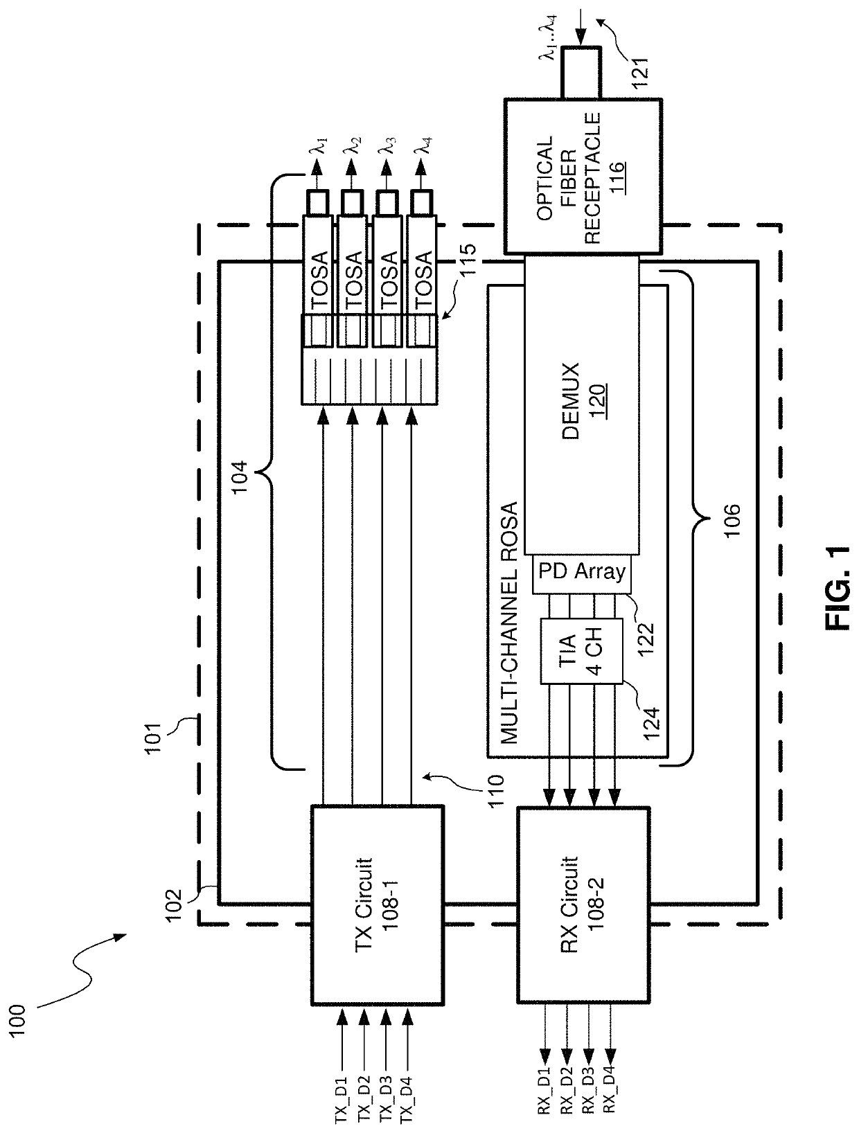
[0015]The present disclosure is generally directed to an optical demultiplexer for use in an optical transceiver module having a truncated profile / shape to increase tolerance and accommodate adjacent optical components. In more detail, the optical demultiplexer comprises a body with at least one truncated corner at the input end. The at least one truncated corner allows the optical demultiplexer to be disposed / mounted, e.g., directly, on a densely populated transceiver substrate, e.g., a printed circuit board (PBC), and provide additional tolerance / space for mounting of circuitry and / or components within the region that would normally be occupied by corner(s) of the optical demultiplexer body. The at least one truncated corner may be introduced in a post-production step, e.g., via cut & polishing, or introduced during formation of the optical demultiplexer using, for instance, photolithography techniques.

[0016]In accordance with an embodiment, the optical demultiplexer comprises an ...


PUM

PropertyMeasurementUnit
widthaaaaaaaaaa
wavelengthsaaaaaaaaaa
transmission distancesaaaaaaaaaa

Abstract

The present disclosure is generally directed to an optical demultiplexer for use in an optical transceiver module having a truncated profile / shape to increase tolerance and accommodate adjacent optical components. In more detail, the optical demultiplexer comprises a body with at least one truncated corner at the input end. The at least one truncated corner allows the optical demultiplexer to be disposed / mounted, e.g., directly, on a densely populated transceiver substrate, e.g., a printed circuit board (PBC), and provide additional tolerance / space for mounting of circuitry and / or components within the region that would normally be occupied by corner(s) of the optical demultiplexer body. The at least one truncated corner may be introduced in a post-production step, e.g., via cut & polishing, or introduced during formation of the optical demultiplexer using, for instance, photolithography techniques.

Description

TECHNICAL FIELD[0001]The present disclosure relates to optical communications, and more particularly, to an optical demultiplexer, such as an arrayed waveguide grating (AWG), with a truncated profile / shape to increase tolerance and accommodate adjacent optical components.BACKGROUND INFORMATION[0002]Optical transceivers are used to transmit and receive optical signals for various applications including, without limitation, internet data center, cable TV broadband, and fiber to the home (FTTH) applications. Optical transceivers provide higher speeds and bandwidth over longer distances, for example, as compared to transmission over copper cables. The desire to provide higher transmit / receive speeds in increasingly space-constrained optical transceiver modules has presented challenges, for example, with respect to thermal management, insertion loss, RF driving signal quality and manufacturing yield.[0003]The data center market for optical transceivers continues to grow, as well as incre...

Claims


Application Information

Patent Timeline
Patent Type & Authority Patents(United States)
IPC IPC(8): G02B6/12G02B6/42G02B6/35G02B6/125H04B10/40
CPCG02B6/3502G02B6/125G02B6/12007H04B10/40G02B6/4215G02B6/29301G02B6/4246G02B6/12009G02B6/428
Inventor LIN, KAI-SHENGCHENG, HAO-CHIANGCAI, ZILIANG
Owner USAA
Learn More