Method for manufacturing a thin-walled part

a manufacturing method and thin-walled technology, applied in the direction of metal-working equipment, workpieces, milling equipment, etc., can solve the problems of long machining time, poor surface quality, long machining time, etc., and achieve the effect of reducing tool wear and improving machining efficiency

Active Publication Date: 2022-05-24
GF MACHINING SOLUTIONS AG
View PDF7 Cites 0 Cited by
  • Summary
  • Abstract
  • Description
  • Claims
  • Application Information

AI Technical Summary

Benefits of technology

[0010]It is an aspect of this invention to provide a method to manufacture a thin-walled part with an improved machining efficiency. It is in particular an objective of this invention to provide a method to manufacture a turbine blade with a reduced tool wear without compromising the productivity.
[0011]In the present invention, a method for manufacture a thin-walled part having curved surfaces, in particular a turbine blade comprises roughing process and semi-finishing process. At least one of the roughing process and the semi-finishing process is accomplished by flank milling. This has the advantage of increasing the material removal rate without violating the constraints such as tool life, the quality of the manufactured part.
[0012]Flank milling is one of the important types of milling, in particular, for manufacturing aircraft structural parts, turbines, blades and several other mechanical parts. Flank milling cuts with the side of the cutting tool and thereby can remove a large amount of material in a single pass. For example, a turbine blade can be quickly obtained by machining a ruling, namely a workpiece in one pass by aligning the side of a cutting tool to the rulings. If point milling is applied, many passes are needed and consequently longer machining time is required. Therefore, flank milling can reduce manufacturing time, enhance the surface quality and reduce cost.
[0013]Roughing is a process in which a large amount of material is removed and the surface quality is poor. Semi-finishing is a process in which a small amount of material is removed in order to achieve high surface quality. When the thin-walled part, for example the turbine blade must be manufactured by milling, roughing the workpiece to obtain components of the blade, such as the platform and the fillet radius of the turbine blade is one of the most critical operation. In order to reduce the machining time and thereby reduce the manufacturing cost per blade, the material removal rate should be high. In know methods, this step is carried out by spiral point milling, which causes a high carbide burn and long machining time. Employing the flank milling can reduce the carbide burns dramatically and at the same time shorten the machining time. Additionally, cutting tools used in flank milling are generally more expensive than the cutting tools for point milling, because cutting teeth along the full length are necessary and solid carbide tooling is used for the stiffness. Thus, reducing the carbide burns can increase the tool life, thereby the cost of the production can be reduced.
[0017]In a preferred embodiment, based on the characteristic data of the cutting tool the operation mode is selected to enable a full-slot milling of at least a part of the turbine blade. Full-slot milling means the workpiece is cut in the entire depth of the workpiece, which leads a high machining sufficiency.
[0018]Dynamic deflection, caused by the chatter of the cutting tool during the machining may substantially affect the machining results of complex, thin-walled part. The milling process under chatter-free condition in the stable mode is highly desired. However, the process damping mode enables the full-slot milling. Even in the process damping mode, the spindle speed is low, the total machining time can still be reduced due to the high material remove rate. In addition, the tool wear is reduced. If the full-slot milling is not operated in this mode, the cutting tool maybe broken. Since the entire tool length is used in the full-slot milling, the cutting forces are much higher than point milling, in which only the tool tip is used. This results in deflection of the cutting tool or part.

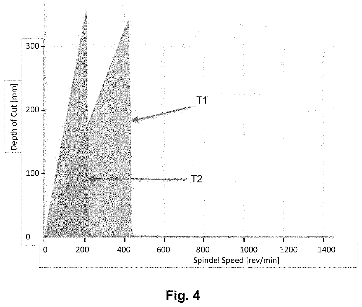
Problems solved by technology

If point milling is applied, many passes are needed and consequently longer machining time is required.
Roughing is a process in which a large amount of material is removed and the surface quality is poor.
In know methods, this step is carried out by spiral point milling, which causes a high carbide burn and long machining time.
Additionally, cutting tools used in flank milling are generally more expensive than the cutting tools for point milling, because cutting teeth along the full length are necessary and solid carbide tooling is used for the stiffness.

Method used


Image

  • Method for manufacturing a thin-walled part
  • Method for manufacturing a thin-walled part
  • Method for manufacturing a thin-walled part

Examples


Embodiment Construction

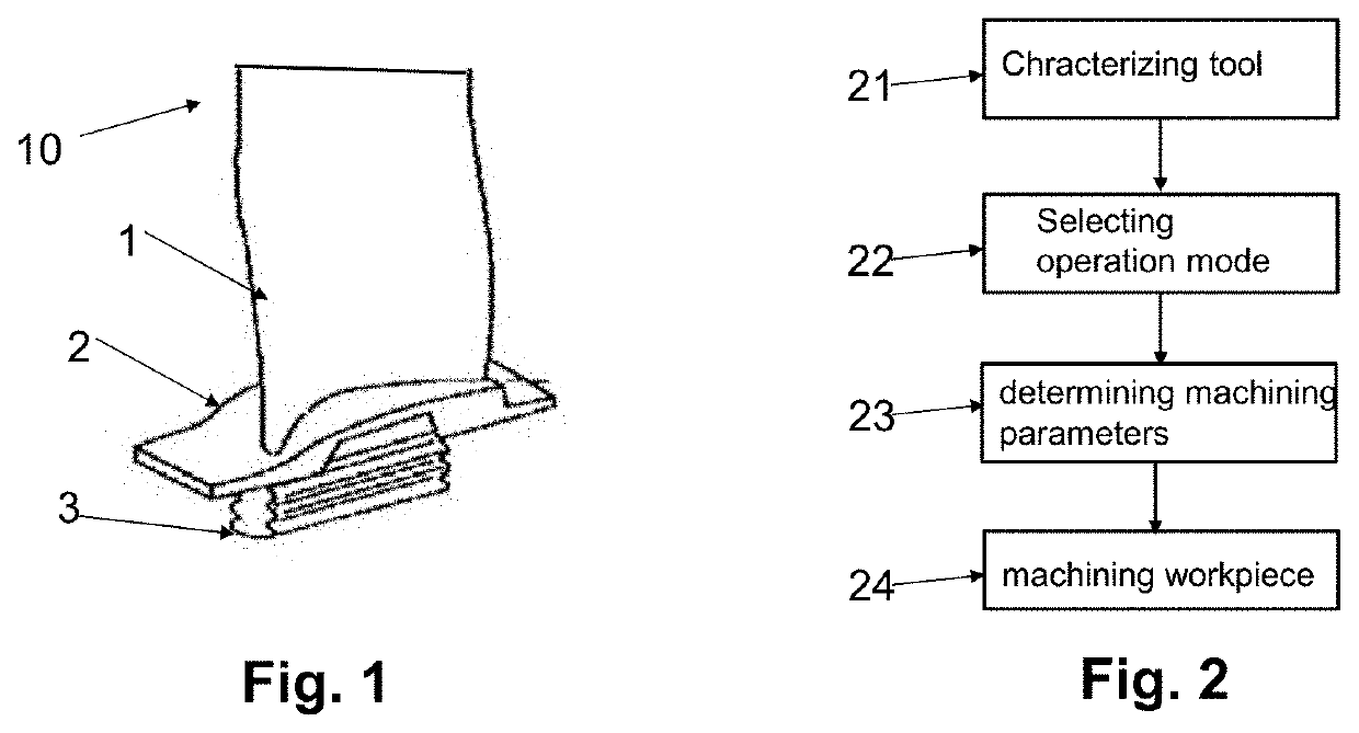
[0035]FIG. 1 illustrates a schematic of a single machined turbine blade 10 including an airfoil 1, a platform 2, and a blade root 3, which can be manufactured by the method of the present invention. However, the method of present invention is not limited to machine turbine blade and not limited to this particular shape of the turbine blade. For example, the turbine blade having additionally a shraud can also be machined by this method.

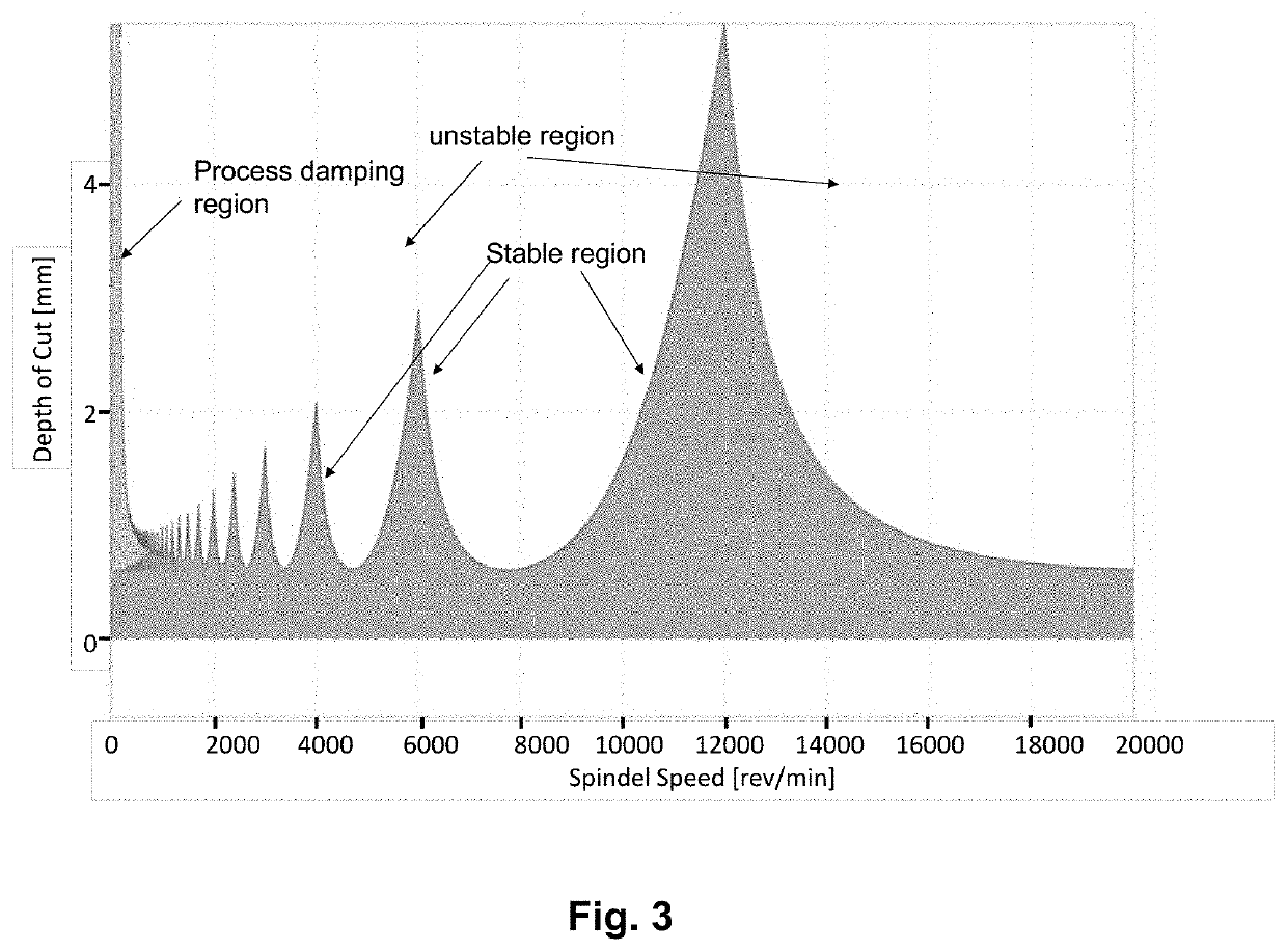
[0036]FIG. 2 shows the main steps included in the method of the present invention: characterizing a cutting tool 21, selecting an operation mode 22, determining machining parameter 23 and machining workpiece 24. Before milling the workpiece by a machine tool, at least one cutting tool used for the milling is characterized for example by a tap testing to identify the critical frequency range regarding the vibration to obtain stability lobes.

[0037]FIG. 3 shows the results of the conducted tap testing for two cutting tools T1 and T2 depicted in stability ...


PUM


Abstract

A method for manufacturing a thin-walled part having curved surfaces, in particular a turbine blade by a machine tool comprising roughing process and semi-finishing process. At least one of the roughing process and the semi-finishing process is accomplished by flank milling.

Description

CROSS-REFERENCE TO RELATED APPLICATION[0001]This application claims the benefit and priority of European Patent Application No. 19 215 452.4 filed Dec. 12, 2020. The entire disclosure of the above application is incorporated herein by reference.FIELD OF THE INVENTION[0002]The present invention is directed to a method for manufacturing a thin-walled part, in particular, a turbine blade. In further, the present invention is directed to a machine tool to manufacture the thin-walled part.BACKGROUND OF THE INVENTION[0003]The process of manufacturing parts or components having a thin-walled and curved surface can be challenging because beside the complex shape to be achieved, for many applications the machined part must fulfill high quality requirement. Therefore, a multi-axis machine tool is needed to accomplish the complex shape. Since the thin-walled workpiece has low stiffness, additional problems can be raised during the machining, such as, process-related static displacements and vi...

Claims


Application Information

Patent Timeline
Patent Type & Authority Patents(United States)
IPC IPC(8): B23C3/18
CPCB23C3/18B23C2220/605B23C2215/44B23C2215/48B23C2215/52B23C2215/56B23C2220/28
Inventor FINGER, ANDREASDAY, TIM
Owner GF MACHINING SOLUTIONS AG
Why Eureka
Try Eureka